EasyManuals Logo

Circutor CVM-MINI SERIES User Manual

Circutor CVM-MINI SERIES
26 pages
To Next Page IconTo Next Page
To Previous Page IconTo Previous Page
Page #7 background imageLoading...
Page #7 background image
Page 7 of 26
2.2.2 Connection diagrams
S2
P2
S1
P1
L1
L2
L3
N
S2
P2
S1
P1
S2
P2
S1
P1
N
Alimentacion
Power Supply
S2
P2
S1
P1
L1
L2
L3
S2
P2
S1
P1
S2
P2
S1
P1
b
B
a
A
b
B
a
A
L1
L2
L3
b
B
a
A
b
B
a
A
S2
P2
S1
P1
S2
P2
S1
P1
Alimentacion
Power Supply
Figure 2. [4-wire / 3-wire - Low Voltage]
Figure 3. [2 voltage transformers -
3 current transformers]
Figure 4. [2 voltage transformers -
2 current transformers]
3 OPERATING MODE
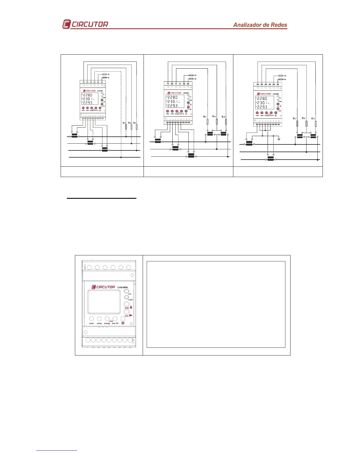
When power is supplied to the CVM-MINI, the equipment will start its software interface
on the screen showing the version of the firmware and its setting. After a few seconds
the equipment is ready to operate and shows all available screens.
Once started the power analyzer will display the programmable electrical parameters
via the measurement Set-up. If there is no previous setting, the analyzer will display the
voltage between phase and neutral for L1, L12 and L1
Ci r c
ut or
UER1 .0 0
Figure 5. CVM-MINI
-
-
-
8 .8 .8 .8
8 .8 .8 .8
8.8.8.8.88
L1
L2
L3
THD
PF
OS
C
I
N
Pd
kvVArCh
Hz
Figure 6. CVM-MINI display - LCD SEGMENTS

Questions and Answers:

Circutor CVM-MINI SERIES Specifications

General IconGeneral
BrandCircutor
ModelCVM-MINI SERIES
CategoryMeasuring Instruments
LanguageEnglish

Related product manuals