11
Instruction Manual
RGU-10A, RGU-100A
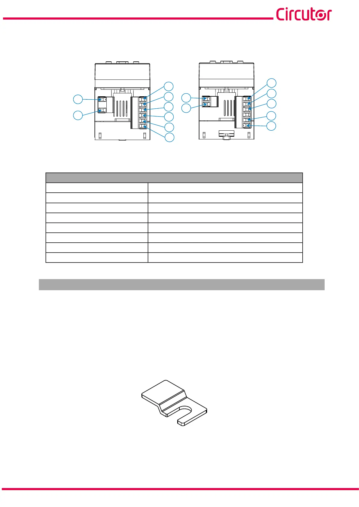
3.4.2. RGU100A
A2
A1
1
2
3
4
5
6
7
8
19
20
22
23
24
Figure 5: Terminals of the RGU-100A: Upper - Lower.
Table 5: List of RGU-100A terminals.
Device terminals
A1: A1, Power supply 7: 1S1, Transformer connection WGC
A2: A2, Power supply 8: 1S2, Transformer connection WGC
1: R1, Trip relay (NO) 19: TRIP/RESET, Input for trigger or external reset
2: R1, Trip relay (NC) 20: TRIP/RESET, Input for trigger or external eset
3: C1, Trip relay (Common) 22: S, GND for RS-485
4: R2, Pre-alarm relay (NO) 23: B-, RS-485
5: R2, Pre-alarm relay (NC) 24: A+, RS-485
6: C2, Pre-alarm relay (Common)
3.5 - WGC TRANSFORMERS
The transformer is designed for wall-mounting or DIN-rail assembly with an accessory for installation.
The WGC is a feed-thru busbar type transformer, where the conductor cables to be measured must
pass through the inner hole or window of the transformer.
3.5.1 PANEL INSTALLATION
For panel installation, 4 clamping clips are provided with the transformer, see Figure 6.
Figure 6: Clamping clip.
The clamping clips must be installed on the WGC, as shown in Figure 7.