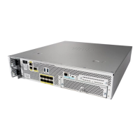
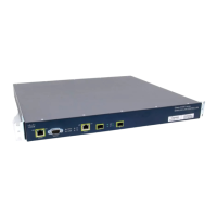
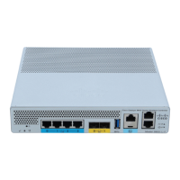
In the all of the above configuration, VLAN10 is not tagged on the switch. All traffic from the switch is
sourced to Port 1 on the controller. APs and client traffic is forwarded to the controller untagged.
APs are connected to the Catalyst switch with these switchport configurations. The switchport can either be
trunked or configured to be an access port.
Switch#sh run int gig 1/0/9
Building configuration...
Current configuration : 132 bytes
!
interface GigabitEthernet1/0/9
switchport trunk encapsulation dot1q
switchport trunk native vlan 10
switchport mode trunk
end
Switch#sh run int gig 1/0/10
Building configuration...
Current configuration : 66 bytes
!
interface GigabitEthernet1/0/10
switchport access vlan 10
end
Switch#
The AP can join the controller and the status of the AP can be verified on the controller. There are two APs
that have joined the controller and can be confirmed by checking the status in this capture:
<CISCO2504> >show ap join stats summary all
Number of APs.............................................. 2
Base Mac AP EthernetMac AP Name IP Address Status
00:22:90:96:69:00 00:22:90:90:ab:d3 AP0022.9090.abd3 10.10.10.103 Joined
ec:44:76:b9:7d:c0 c4:7d:4f:3a:e3:78 APc47d.4f3a.e378 10.10.10.105 Joined
<CISCO2504> >show ap summary
Number of APs.................................... 2
Global AP User Name.............................. Not Configured
Global AP Dot1x User Name........................ Not Configured
AP Name Slots AP Model Ethernet MAC Location
−−−−−−−−−−−−−−−− −−−−− −−−−−−−−−−−−−−−−− −−−−−−−−−−−−−−−−− −−−−−−−−−−−−−−−−
AP0022.9090.abd3 2 AIR−LAP1142N−A−K9 00:22:90:90:ab:d3 default location
APc47d.4f3a.e378 2 AIR−CAP3502E−A−K9 c4:7d:4f:3a:e3:78 default location
 Loading...


