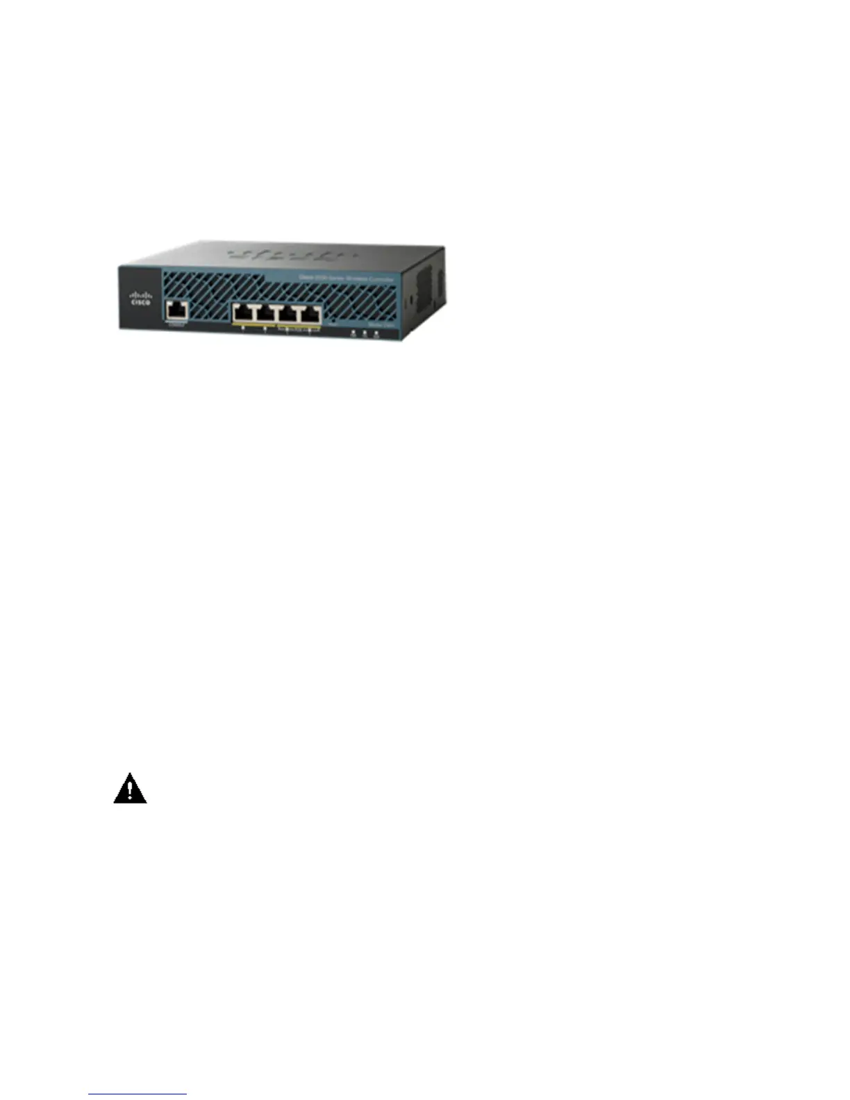
The Cisco 2500 Series Wireless Controller has 1 GB system memory. Two types of memory devices are
supported in order to store software images. The boot flash contains the boot code, and the compact flash
contains the application code that can store multiple images. The front panel houses four Gigabit Ethernet
ports. Two of the ports are 802.3af capable. All ports will transfer the traffic to/from the wireless network.
The Power over Ethernet (PoE) ports on the Cisco 2500 Series Wireless Controller will not support directly
attached APs.
The Cisco 2500 Series Wireless Controller is powered by an external 48VDC power brick. The power brick
can handle power input from 110VAC to 240VAC.
Basic Configuration of the Cisco 2500 Series Wireless
Controller
These tools and information are needed before you can install the controller:
Wireless Controller hardware:
Controller with factory−supplied power cord and mounting hardware♦
Network, operating system service network, and AP cables as required for the command−line
interface (CLI) console
♦
VT−100 terminal emulator on the CLI console (PC, laptop, or palmtop)♦
Null modem serial cable to connect the CLI console and controller♦
•
Local TFTP server (required for downloading operating system software updates). Cisco uses an
integral TFTP server. This means that third−party TFTP servers cannot run on the same workstation
as the Cisco WCS because Cisco WCS and third−party TFTP servers use the same communication
port.
•
If the controller is brought up for the first time with no prior configuration, it automatically enters into a
wizard, which will ask you a series of configuration information. The wizard first will first prompt for user ID
and password. This wizard cannot be bypassed and you must enter all the information it asks.
Caution: Do not connect a PoE cable to the console port. Doing so will damage the controller.
Controller Configuration through CLI
Before you can configure the controller for basic operations, you need to connect it to a PC that uses a
VT−100 terminal emulator (such as HyperTerminal, ProComm, Minicom, or Tip). Complete these steps in
order to connect the PC to the controller's console port:
Plug the RJ−45 connector on a null−modem serial cable into the controller's console port and the
other end of the cable into the PC's serial port.
1.
Start the PC's terminal emulation program.2.
Configure the terminal emulation program for these parameters:3.

 Loading...