6 Installing Cisco AC and DC Power Supplies in Cisco 2500 Series Routers
Replacing the Cover
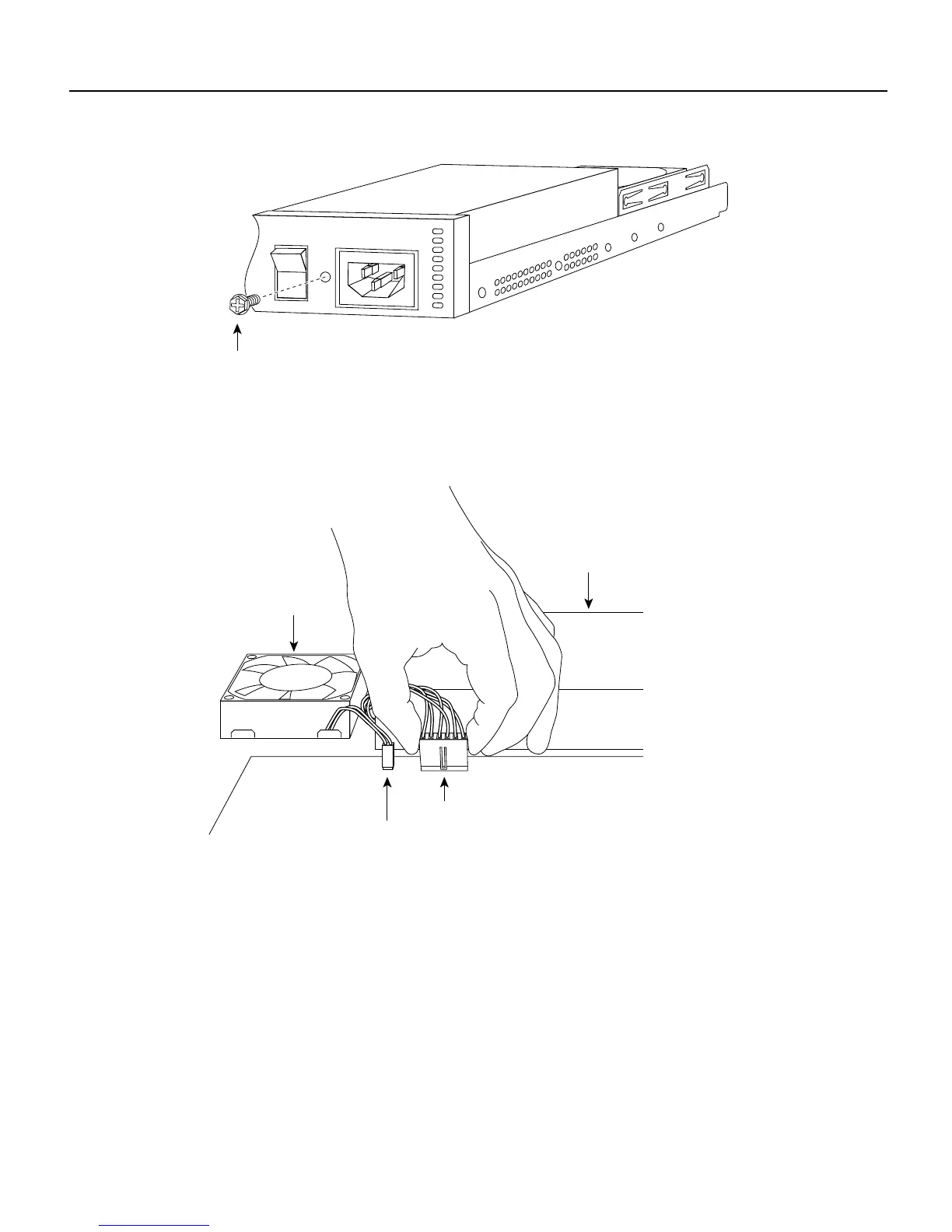
Figure 6 Installing the Screw
Step 3
Connect the power connector from the system board. Grasp the sides of the power
connector and gently push downward while rocking the connector side to side.
(See Figure 7.)
Figure 7 Connecting the Power Connector
Replacing the Cover
Take the following steps to replace the cover:
Step 1 Position the two chassis sections, as shown in Figure 8.
Step 2 Referring to Figure 8, press the two chassis sections together and ensure the following:
• The top section fits into the rear of the bottom section. (See A in Figure 8.)
• The bottom section fits into the front of the top section. (See B in Figure 8.)
• Each side of the top and bottom sections fits together. (See C in Figure 8.)
H9079
Input: 100-240VAC
Freq: 50/60 Hz
Current: 1.2-0.6A
Watts: 40W
0
1
Screw
H9247
Power connector
Fan connector
Fan
AC power supply
 Loading...