1-10
Cisco 2600 Series Routers Hardware Installation Guide
OL-2171-06
Chapter 1 Overview of Cisco 2600 Series Routers
Interface Numbering
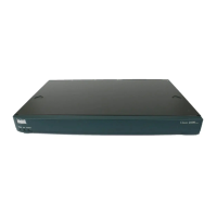
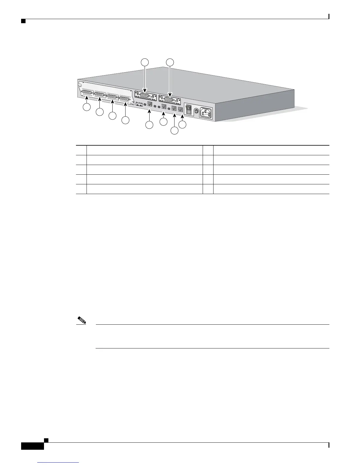
Figure 1-11 Interface Numbering in Chassis with 1-RU Height
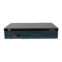
Figure 1-12 shows a router of 2-RU height with:
• A 2-port T1 network module in slot 1 (containing the following ports: T1 1/0 and T1 1/1)
• Two built-in Ethernet 10/100 interfaces—Fast Ethernet 0/0 and Fast Ethernet 0/1
• A WIC in each WIC slot (containing interfaces Serial 0/0 and Serial 0/1 in physical slot W0,
interface Serial 0/2 in physical slot W1, and interface BRI 0/0 in physical slot W2)
–
If physical slot W0 is empty and physical slot W1 contains a 1-port serial WIC, the interface
number in the WIC is numbered Serial 0/0.
–
If slot W0 contains a 2-port serial WIC and slot W1 contains a 1-port serial WIC, the interfaces
in physical slot W0 are numbered Serial 0/0 and Serial 0/1, and the interface in physical slot W1
is numbered Serial 0/2.
–
If slot W0 contains a 2-port serial WIC and slot W1 contains a 1-port BRI WIC, the interfaces
in physical slot W0 are numbered Serial 0/0 and Serial 0/1, and the interface in physical slot W1
is numbered BRI 0/0.
Note The slot number for all WIC interfaces is always 0. (The W0 and W1 slot designations are for
physical slot identification only.) Interfaces in the WICs are numbered from right to left, starting
with 0/0 for each interface type, regardless of which physical slot the WICs are installed in.
1 WIC Slot 1 (Serial 0/1) 6 Ethernet 0/1 (Optionally: Token Ring 0/0)
2 WIC Slot 0 (Serial 0/0) 7 Network Module Port 0 (Serial 1/0)
3 Auxiliary Port 8 Network Module Port 1 (Serial 1/1)
4 Console Port 9 Network Module Port 2 (Serial 1/2)
5 Ethernet 0/0 10 Network Module Port 3 (Serial 1/3)
28308
Cisco 2612
1
00-2
40
V
– 1A
5
0/60
H
z 4
7
W
W
1
CN/LP
2
1
0
3
RXC RXD
TX
C TXD
CN/LP RXC
RXD
TXC
TXD
CN/LP
RXC RXD TXC
TXD
CN/LP RXC RXD TXC
TXD
E
N
SERIAL
A/S
W
0
S
E
R
IA
L
C
O
N
N
W0
SER
IAL
C
ON
N
AUX
CONSOLE
ETHERNET 0/0
ACT
LINK
ACT
TOKEN RING 0/0
LINK
W0
3
4
5
6
7
8
9
10
1
2
 Loading...