1-3
Cisco 2600 Series Routers Hardware Installation Guide
OL-2171-06
Chapter 1 Overview of Cisco 2600 Series Routers
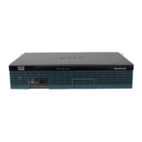
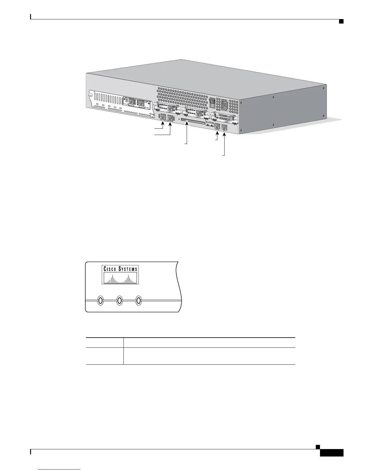
Reading the Front-Panel LEDs
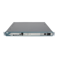
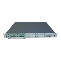
Figure 1-2 Cisco 2600 Series Router Rear Panel—Example of 2RU Router
Reading the Front-Panel LEDs
The LEDs indicate the current operating condition of the router. By observing the LEDs, you can note
any fault condition that the router is encountering, and then contact your system administrator or
customer service, when necessary.
Figure 1-3 and Figure 1-4 show the locations of the LEDs on the front panel of Cisco 2600 series routers.
Table 1-3 and Table 1-3 describe these LEDs.
Figure 1-3 Cisco 2600 Series Routers with 1-RU Chassis Height—Front-Panel LEDs
72056
S
E
E
M
A
N
U
A
L
B
E
F
O
R
E
IN
S
T
A
LL
A
T
IO
N
AL
CD
LP
RD
TD
S
E
E
M
A
N
U
A
L
B
E
F
O
R
E
IN
S
T
A
L
L
A
T
IO
N
D
S
U
56K
AL
CD
LP
RD
TD
S
E
E
M
A
N
U
A
L
B
E
F
O
R
E
IN
S
T
A
L
L
A
T
IO
N
D
S
U
56K
EN
V0
B
ANK 4
BA
NK 3
BA
NK 2
BAN
K 1
B
ANK
0
NM-HDV
VW
IC
2MFT-E1
S
E
E
M
A
N
U
A
L
B
E
F
O
R
E
INS
T
ALL
A
TIO
N
C
TRLR
E2
CTR
LR E1
AL
LP
CD
FastEthernet 0/1
FastEthernet 0/0
Compact Flash slot
Console
port
Auxiliary
port
C
O
N
S
O
L
E
A
U
X
F
A
S
T
E
T
H
E
R
N
E
T
0
/1
F
A
S
T
E
T
H
E
R
N
E
T
0
/0
ACT
100 Mbps
LINK
ACT
100 Mbps
LINK
CF1
CISCO2691
Table 1-2 Cisco 2600 Series Routers with 1-RU Chassis Height—Front-Panel LED Descriptions
LED Description
POWER Indicates the router’s operating status. Comes on when power is
supplied to the router and the router is operational.
POWER RPS ACTIVITY
H11660
 Loading...