8Cisco 7000 Front Chassis Panel and LED Board and Replacement
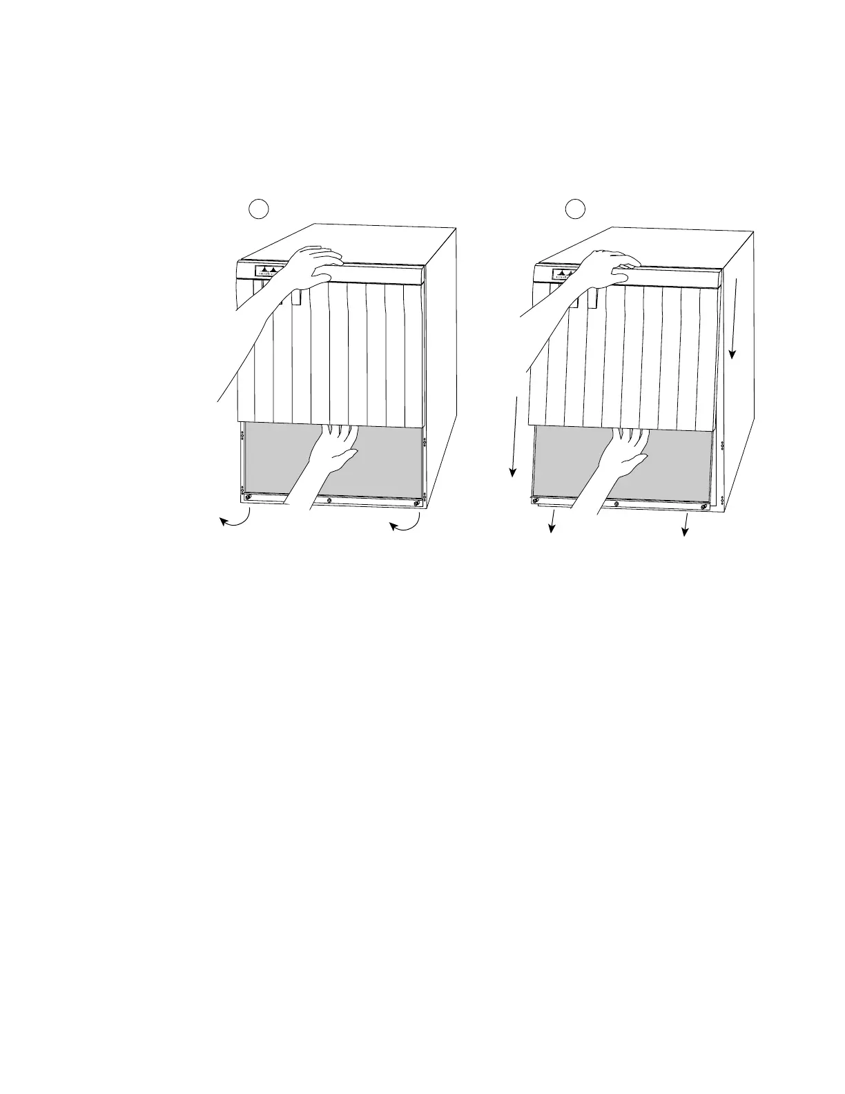
Step 3: On the top front panel, use a screwdriver to loosen the two captive screws at
the bottom edge of the panel frame.
Step 4: Place one hand against the top front center of the panel to brace it (see
Figure 6a). The top of the panel acts as a pivot point when you pull the
bottom out and away from the chassis.
Figure 6 Removing the Top Front Panel
Step 5: With your other hand, grasp the front of the panel by inserting your fingers
into the opening on the underside of the bezel (see Figure 6a).
Step 6: While pushing slightly against the top of the panel to constrain it, pivot the
bottom edge of the frame outward about two inches (see Figure 6a). Because
of the tightly compressed EMI shielding, you will have to use significant force
to pull the bottom of the panel outward. However, be careful that you do not
pull the panel more than two inches away from the chassis, or you can damage
the inner bezel or LED board.
Step 7: When the bottom of the frame clears the chassis opening, keep your hands in
the same positions and pull the panel downward and off the chassis (see
Figure 6b).
Replacing the Panels
To replace the front panels, perform the following steps:
Step 1: Grasp the sides of the top panel with both hands (see Figure 6a).
Cisco 7000
UPPER
POWER
LOWER
POWER
NORMAL
Cisco 7000
UPPER
POWER
LOWER
POWER
NORMAL
H1459a
a
b