1-111
Cisco Integrated Services Router Hardware Installation Guide
Chapter 1 Product Overview
Cisco 860, 880, 890 Series
Caution The primary WAN port is designed for an RJ-11 or RJ-14 connector only. Damage to the
primary WAN port may occur if a non-RJ-11 or RJ-14 connector is inserted.
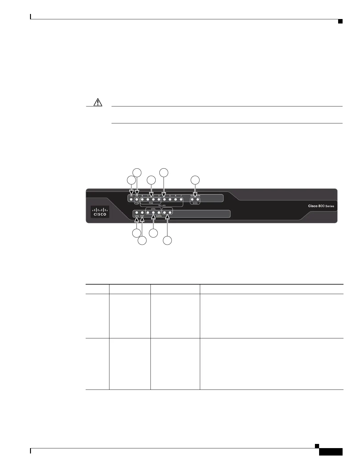
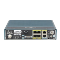
Figure 1-72 shows the front panel of the Cisco 897VAB-K9 ISR.
Figure 1-72 Front panel of the Cisco 897 VAB-K9 ISR
Table 1-39 describes the LEDs for the Cisco 897VAB-K9 ISR.
1. 1.ADSL and VDSL (up to 17a) single-pair functionality uses the center pair of pins in the RJ-11 connector. VDSL 30a single
pair functionality makes use of the pins just adjacent to the center pins. VDSL Bonding makes use of both the center pair pins
& those just adjacent to the center pair to provide the 2 bonded VDSL lines. For more information, see Cisco 890 Series
Integrated Services Routers Data Sheet.
2. 2.Ports 0 through 3 can be configured as POE, which is an optional feature for this model. If this feature is not configured
with the factory order, you must order and install it to enable the PoE function.
364227
CD0 CD1 B1 B2
ISDN
1 3
2
4
5
6
7
8
9
Table 1-39 LED Descriptions for the Cisco 897VAB-K9 ISR
Number LED Color Description
1 Power OK Green On—DC power is being supplied to the router and the
Cisco IOS software is running.
Blinking—Boot up is in process, or the router is in ROM
Monitor (ROMMON) mode.
Off—Power is not supplied to the router.
2 PoE OK Green/Yellow Off—Both POE card & POE power supply are not
present.
Yellow On—Either POE card or POE power supply is
not present.
Green On—Both POE card & POE power supply are
present.