10
Access Point Mounting Instructions
OL-166451-01
Grounding an Access Point
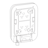
Step 3 Pull approximately 9 inches of Ethernet and power cable through the mounting bracket. Route the cables
through the main cable access hole and then through the smaller access hole as shown in Figure 8.
Step 4 Connect the Ethernet and power cables to the access point.
Step 5 Align the access point feet over the keyhole mounting slots on the mounting bracket.
Step 6 Slide the access point onto the mounting bracket until it clicks into place.
Step 7 Attach the T-rail clips on each end of the T-bar box hanger to the ceiling rails. Make sure the clips are
securely attached to the T-rails.
Step 8 Replace the ceiling tile.
Grounding an Access Point
Grounding is not always required for indoor installations because Cisco Aironet access points are
classified as low-voltage devices and do not contain internal power supplies. We recommend that you
check your local and national electrical codes to see if grounding is a requirement.
Although grounding is not mandatory for indoor access points, it is required in certain scenarios. It has
been observed that an ungrounded indoor access point that is mounted too close to an electromagnetic
source of interference (such as a fluorescent light that is on) may reboot suddenly or suffer hardware
damage. This occurs even if the indoor AP is in close proximity to the electromagnetic source of
interference, and not touching the source. Grounding the corresponding access point or the mounting
bracket helps prevent this issue from occurring. We recommend that a certified electrical technician
verify whether your installation requires grounding.
If grounding is required in your area or you wish to ground your access point, follow these steps.
Step 1 Find a suitable building grounding point as close to the access point as possible.
Step 2 Connect a user-supplied ground wire to the building grounding point. The wire should be a minimum of
#14AWG assuming a circuit length of 25 ft (30.5 cm). Consult your local electrical codes for additional
information.
Step 3 Route the ground wire to the access point.
Step 4 Attach the wire to a suitable grounding O-ring lug.
Step 5 Crimp or solder the wire to the lug.
Step 6 Insert the grounding post screw into the O-ring lug and install it on the mounting bracket as shown in
Figure 10.