4
2 Connect and Power Up the Access Point (continued)
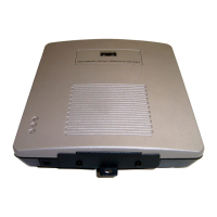
350 Series Access Points
Note The following steps apply to 350 Series access points with metal or plastic cases.
Step 1 Adjust the access point antennas. Step 1 on page 3 of this guide provides guidelines for
positioning the antennas.
Step 2 Consult the drawing above and choose the power supply option you will use.
Step 3 Connect the Ethernet cable to the Ethernet connector on the back of the access point.
Connect the other end of the Ethernet cable to one of the following:
• A switch with inline power, such as a Cisco Catalyst 3524-PWR-XL
• An inline power switch power panel, such as a Cisco Catalyst Inline Power Patch Panel
• The end of a Cisco Aironet power injector labeled To AP/Bridge and the end labeled To
Network to the 10/100 Ethernet LAN.
Caution The power injector is designed for 350 series access points only. Using the power
injector with other Ethernet devices can damage the equipment.
Power
cord
Universal
power supply
S
Y
S
T
R
P
S
D
U
P
L
X
M
O
D
E
S
P
E
E
D
U
T
I
L
S
T
A
T
1
2
3
4
5
6
7
8
9
1
0
1
1
1
2
1
3
1
4
1
5
1
6
1
7
1
8
1
9
2
0
2
1
2
2
2
3
2
4
2
3
2
4
1
0
B
a
s
e
-
T
/
1
0
0
B
a
s
e
-
T
X
1
0
0
B
a
s
e
-
F
X
C
a
t
a
l
y
s
t
2
9
5
0
S
E
R
I
E
S
S
Y
S
T
R
P
S
D
U
P
L
X
M
O
D
E
S
P
E
E
D
U
T
I
L
S
T
A
T
1
2
3
4
5
6
7
8
9
1
0
1
1
1
2
1
3
1
4
1
5
1
6
1
7
1
8
1
9
2
0
2
1
2
2
2
3
2
4
2
3
2
4
1
0
B
a
s
e
-
T
/
1
0
0
B
a
s
e
-
T
X
1
0
0
B
a
s
e
-
F
X
C
a
t
a
l
y
s
t
2
9
5
0
S
E
R
I
E
S
S
Y
S
T
R
P
S
D
U
P
L
X
M
O
D
E
S
P
E
E
D
U
T
I
L
S
T
A
T
1
2
3
4
5
6
7
8
9
1
0
1
1
1
2
1
3
1
4
1
5
1
6
1
7
1
8
1
9
2
0
2
1
2
2
2
3
2
4
2
3
2
4
1
0
B
a
s
e
-
T
/
1
0
0
B
a
s
e
-
T
X
1
0
0
B
a
s
e
-
F
X
C
a
t
a
l
y
s
t
2
9
5
0
S
E
R
I
E
S
S
Y
S
T
R
P
S
D
U
P
L
X
M
O
D
E
S
P
E
E
D
U
T
I
L
S
T
A
T
T
O
A
P
/
B
R
I
D
G
E
T
O
N
E
T
W
O
R
K
Switch with
inline power
Power injector
Access Point
Switch
(without inline power)
Switch
(without inline power)
Inline Power
Patch Panel
Option 1 Option 2 Option 3
 Loading...