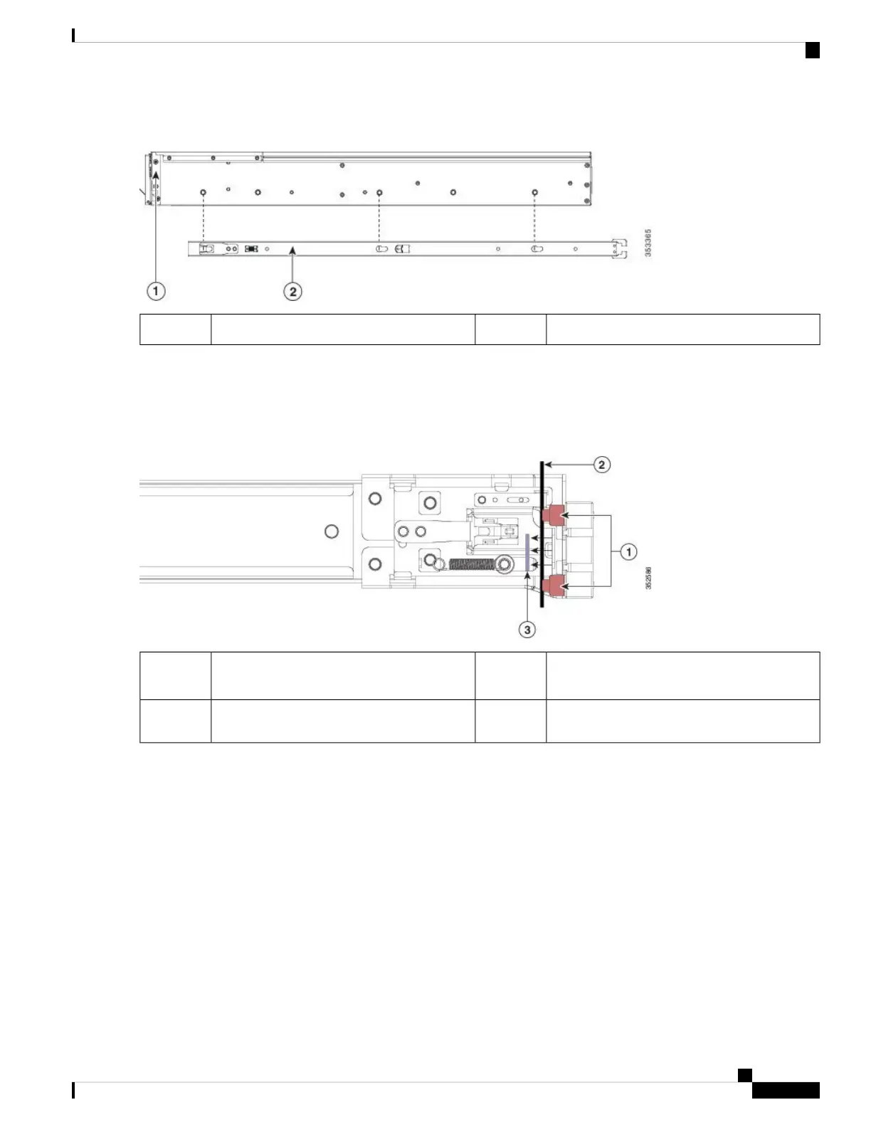
Figure 8: Attaching the Inner Rail to the Side of the Server
Inner rail2Front of server1
Step 2 Open the front securing plate on both slide-rail assemblies. The front end of the slide-rail assembly has a spring-loaded
securing plate that must be open before you can insert the mounting pegs into the rack-post holes.
On the outside of the assembly, push the green-arrow button toward the rear to open the securing plate.
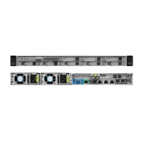
Figure 9: Front Securing Mechanism, Inside of Front End
Securing plate shown pulled back to the open
position
3Front mounting pegs1
-Rack post between mounting pegs and opened
securing plate
2
Step 3 Install the outer slide rails into the rack:
a) Align one slide-rail assembly front end with the front rack-post holes that you want to use.
The slide rail front-end wraps around the outside of the rack post and the mounting pegs enter the rack-post holes
from the outside-front.
The rack post must be between the mounting pegs and the open securing plate.
Note
b) Push the mounting pegs into the rack-post holes from the outside-front.
c) Press the securing plate release button, marked PUSH. The spring-loaded securing plate closes to lock the pegs in
place.
d) Adjust the slide-rail length, and then push the rear mounting pegs into the corresponding rear rack-post holes. The
slide rail must be level front-to-rear.
The rear mounting pegs enter the rear rack-post holes from the inside of the rack post.
Cisco APIC M4/L4 Server Installation and Service Guide
23
Installing the Server
Installing the Server in a Rack