25
To connect an alarm device to the alarm port, follow this procedure:
Note The alarm connector is a 3-wire connector that plugs into a receptacle in the rear of the chassis. The connector is
provided in the accessory kit that ships with the universal gateway.
Step 1 Insert the three-pin alarm port connector (included in the accessory kit) into the alarm port terminal block.
Step 2 Strip a minimum 1/4 in. (0.625 cm) off the wire insulation to connect the stranded wires to the alarm connector. The
maximum insulation strip length is 0.31 in. (0.78 cm).
Note Use stranded Number 12 or 14 AWG copper wires to connect an alarm device to the alarm port connector.
Step 3 Secure the wires to the alarm connector with the screws on the connector.
Caution The maximum tightening torque on the screws is 7 in.-lb (0.79 N-m).
Connecting Alarm Device to Cisco AS5350
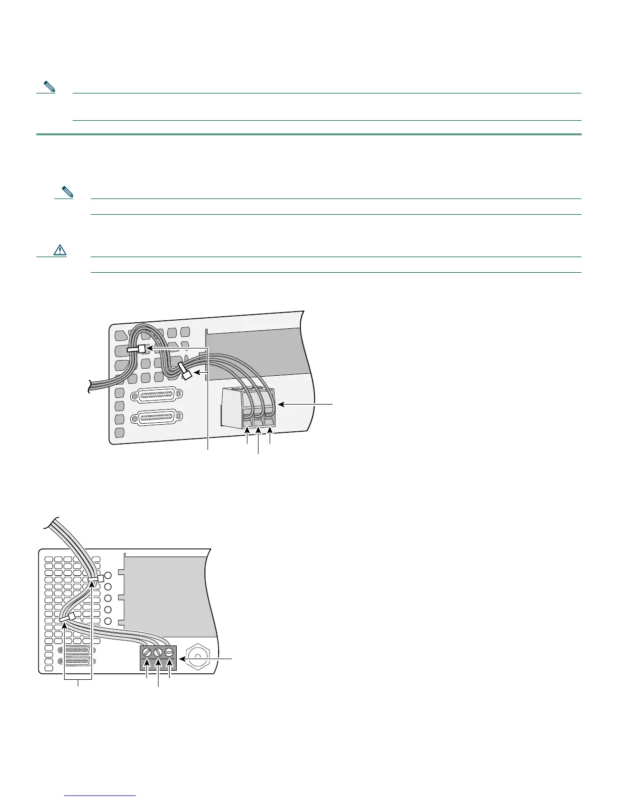
Connecting Alarm Device to Cisco AS5400
Step 4 Attach two cable ties to the chassis and connect the wires to the cable ties.
Step 5 Attach the alarm wires to the alarm device.
35967
Alarm port
connector
To alarm device
Cable ties
#1
#2
#3
35145
Alarm port
connector
Cable ties
#1
#2
#3