Maintenance and Upgrade Procedures for the ASA 5500-X
Remove and Install the Power Supply
Cisco ASA 5512-X, ASA 5515-X, ASA 5525-X, ASA 5545-X, and ASA 5555-X Hardware Installation Guide
59
Procedure
1. Disconnect all cables from the SFP.
Warning: Because invisible laser radiation may be emitted from the aperture of the port when no cable is
connected, avoid exposure to laser radiation and do not stare into open apertures. Statement 70
Caution: Do not pull on the cabling in an attempt to remove the SFP.
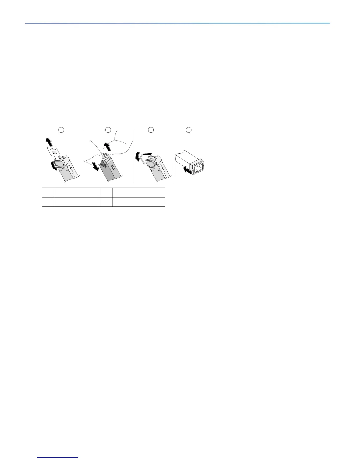
2. Disconnect your particular SFP latch, as shown in Figure 15.
Figure 15 Disconnecting SFP Latch Mechanisms
3. Grasp the SFP on both sides, and remove it from the port.
Remove and Install the Power Supply
This section describes how to remove and install power supply modules.
Remove and Install the AC Power Supply, page 59
Install the DC Input Power, page 61
Remove and Install the DC Power Supply, page 65
Remove and Install the AC Power Supply
Note: This procedure applies only to the chassis with a removable AC power suppl: ASA 5545-X and ASA 5555-X.
If only one power supply is installed, make sure that it is installed in slot 0 (left slot) and that slot 1 (right slot) is
covered with a slot cover.
Caution: If you remove a power supply, replace it immediately to prevent disruption of service.
Caution: If the chassis is subjected to environmental overheating, it shuts down and you must manually
power cycle it to turn it on again.
Warning: This unit has more than one power supply connection; all connections must be removed completely
to completely remove power from the unit. Statement 102
Warning: This product relies on the building’s installation for short-circuit (overcurrent) protection. Ensure
that the protective device is rated not greater than: 120 VAC, 20A U.S. (240 VAC, 10A international). Statement
1005
To remove and install an AC power supply, follow these steps.
1 Mylar tab 2 Actuator/Button
3 Bale-clasp 4 Plastic collar
 Loading...