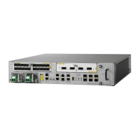
Table 14: Alphanumeric Displays and LEDs at System Startup
Display Contents/LED Status and MeaningType of IndicatorComponent
INIT—Card is inserted and microcontroller is initialized
BOOT—Board is powered on and CPU is booting
IMEM—Start initializing memory
IGEN—Start initializing the board
ICBC—Start initializing communication with the microcontroller
PDxy—Loading programmable devices (x = FPGA, y = ROMMON)
PSTx—Power on self test x
RMN—All tests are finished and ROMMON is ready for commands
LOAD—Downloading Minimum Boot Image (MBI) image to CPU
MBI—Starting execution of MBI
IOXR—Cisco IOS XR software is starting execution
ACTV—RSP role is determined to be active RSP
STBY—RSP role is determined to be standby RSP
PREP—Preparing disk boot
Alphanumeric displayRSP card
Cisco ASR 9000 Series Aggregation Services Router Hardware Installation Guide
200
Troubleshooting the Installation
Identifying Startup Issues

 Loading...