 Loading...


Do you have a question about the Cisco ATA 186 and is the answer not in the manual?
| Operating Temperature | 32°F to 104°F (0°C to 40°C) |
|---|---|
| Protocol | SIP, H.323 |
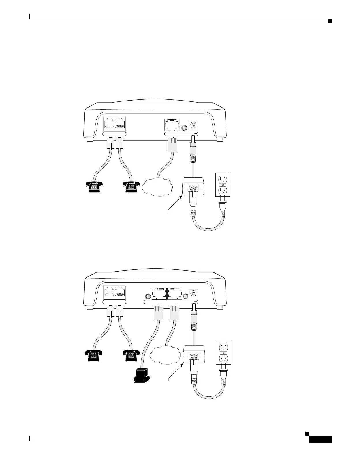
| Network Interface | 10/100BASE-T Ethernet |
| Audio Codec Support | G.729a, G.723.1 |
| Power Supply | 5V DC |
| Weight | 0.23 kg (0.5 lb) |
| Relative Humidity | 10 to 90% noncondensing |
| Ports | 2 RJ-11 FXS ports |