162 Cisco LAN Switching Configuration Handbook
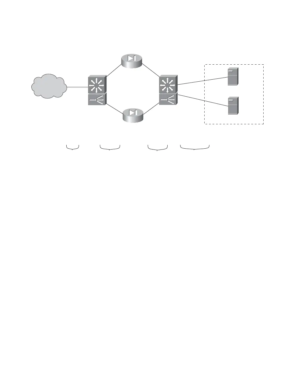
The firewall farm consists of two real firewalls. Their “outside” (unprotected) interfaces
are at 192.168.1.2 and 192.168.1.3. Their “inside” (protected) interfaces are at
192.168.100.2 and 192.168.100.3. On the outside, the default gateway is 10.5.1.1, and the
external SLB device is at 10.5.1.2.
The internal SLB device performs firewall load balancing for outbound traffic to the fire-
wall farm. As well, it provides normal server load balancing for an internal server farm.
The real servers are 10.70.1.10 and 10.70.1.20, and the virtual server appears as 10.5.1.80.
Ping probes are used by both external and internal SLB devices to test for firewall opera-
tion. An HTTP probe tests each of the real servers in the server farm. These use the
default GET method and are sent every 240 seconds.
The configuration for the external load-balancing device is shown first:
(global) ip slb firewallfarm Outside
(firewall-farm) real 192.168.1.2
(real-firewall) weight 8
(real-firewall) probe Ping1
(real-firewall) inservice
(real-firewall) exit
(firewall-farm) real 192.168.1.3
(real-firewall) weight 8
(real-firewall) probe Ping2
(real-firewall) inservice
(real-firewall) exit
(firewall-farm) inservice
(firewall-farm) exit
“Servers”
Catalyst 6000
SLB
Catalyst 6000
SLB
Firewall
Firewall
Out
In
Out
In
Internet
10.5.1.2
Gateway
10.5.1.1
192.168.1.2
192.168.100.2
192.168.1.1
VLAN 10
VLAN 100
VLAN 101
VLAN 102
192.168.100.3
192.168.100.1
Virtual Server
10.5.1.80
10.70.1.10
10.70.1.20
10.70.1.1
192.168.1.3
Figure 10-4 Network Diagram for the Firewall Load-Balancing Example