EasyManuals Logo

Cisco Catalyst 3560-X Series User Manual

Cisco Catalyst 3560-X Series
22 pages
To Next Page IconTo Next Page
To Previous Page IconTo Previous Page
Page #12 background imageLoading...
Page #12 background image
12
Catalyst 3750-X and 3560-X Switch Getting Started Guide
OL-19590-01
Installing the Switch
Caution To comply with the Telcordia GR-1089 Network Equipment Building Systems (NEBS) standard for
electromagnetic compatibility and safety, connect the Ethernet cables only to intrabuilding or
nonexposed wiring or cabling.
Note The grounding architecture of this product is DC-isolated (DC-I).
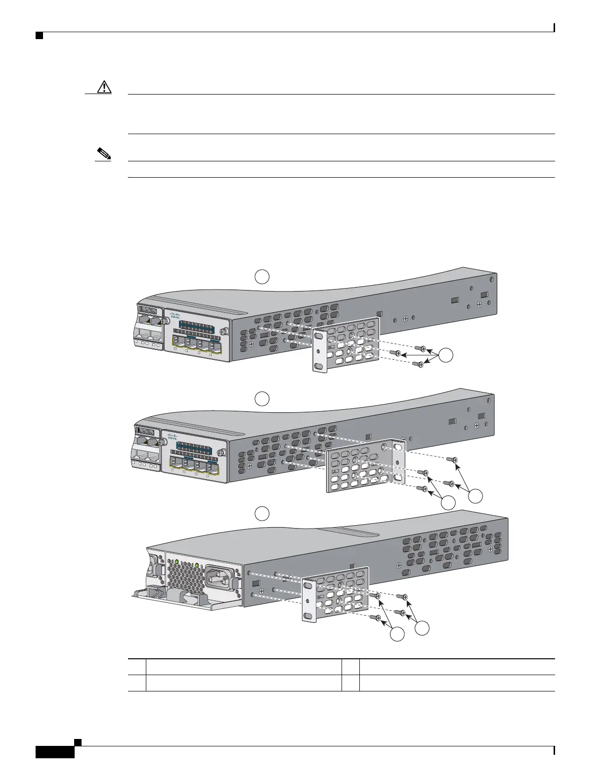
Attaching the Brackets
Use three (for front-mount) or four (for mid- or rear-mount) number-8 Phillips flat-head screws to attach
the long side of each bracket to the switch in one of these mounting positions.
1 Front-mounting position 3 Mid-mounting position
2 Number-8 Phillips flat-head screws 4 Rear-mounting position
5WAC
AC OK
C3KX-PWR-715WAC
PS OK
Catalyst 3750-X PoE+48
8
9
10
11
12
C3KX-NM-10G
NETWORK
MODULE
G1
G2/TE1
G3
G4/TE2
Catalyst 3750-X PoE+48
8
9
10
11
12
C3KX-NM-10G
NETWORK
MODULE
G1
G2/TE1
G3
G4/TE2
207656
1
2
3
4
2
2
2
2

Questions and Answers:

Question and Answer IconNeed help?

Do you have a question about the Cisco Catalyst 3560-X Series and is the answer not in the manual?

Cisco Catalyst 3560-X Series Specifications

General IconGeneral
Product TypeSwitch
LayerLayer 3
ModelCisco Catalyst 3560-X Series
Ports24 or 48 x 10/100/1000 Ethernet ports
StackingYes, with FlexStack
Power SupplyInternal power supply (redundant power supply optional)
PoEAvailable on select models (PoE and PoE+)
MAC Address Table SizeUp to 16, 000 entries
Layer 3 FeaturesRIP, OSPF, EIGRP, PIM
Security FeaturesACLs, 802.1X
ManagementCLI, SNMP, Web GUI
Operating Humidity10 to 95% (noncondensing)
Dimensions4.4 x 44.5 x 37.8 cm

Related product manuals