7
Catalyst 3750-X and 3560-X Switch Getting Started Guide
OL-19590-01
Running Express Setup
Step 10
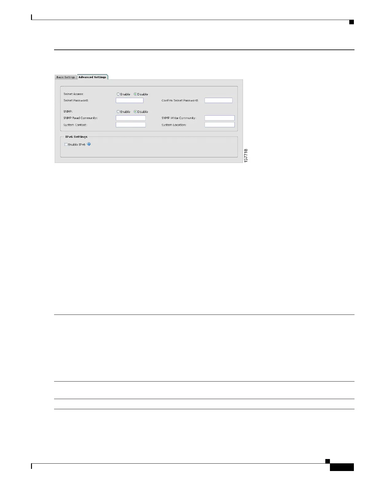
(Optional) You can select the Advanced Settings tab on the Express Setup window and enter the advanced settings
now or enter them later by using the device manager interface.
• In the Telnet Access field, click Enable if you are going to use Telnet to manage the switch by using the
command-line interface (CLI). If you enable Telnet access, you must enter a Telnet password.
• In the Telnet Password field, enter a password. The Telnet password can be from 1 to 25 alphanumeric
characters, is case sensitive, allows embedded spaces, but does not allow spaces at the beginning or end. In the
Confirm Telnet Password field, re-enter the Telnet password.
• In the SNMP field, click Enable to enable Simple Network Management Protocol (SNMP). Enable SNMP only
if you plan to manage switches by using CiscoWorks 2000 or another SNMP-based network-management
system.
• If you enable SNMP, you must enter a community string in the SNMP Read Community field, the SNMP Write
Community field, or both. SNMP community strings authenticate access to MIB objects. Embedded spaces are
not allowed in SNMP community strings. When you set the SNMP read community, you can access SNMP
information, but you cannot change it. When you set the SNMP write community, you can both access and
change SNMP information.
• In the System Contact and System Location fields, enter a contact name and the wiring closet, floor, or building
where the switch is located.
• (Optional) In the Enable IPv6 field, click Enable to enable IPv6 on the switch.
Note Enabling IPv6 restarts the switch when you complete Express Setup.
Step 11
Click Submit to save your changes and to complete the initial setup.
After you click Submit:
• The switch is configured and exits Express Setup mode.
• The browser displays a warning message and tries to connect with the earlier switch IP address. Typically,
connectivity between the PC and the switch is lost because the configured switch IP address is in a different
subnet from the IP address on the PC.
For more information about Express Setup fields, see the online help for the Express Setup window.
Step 12
Disconnect the switch from the PC, and install the switch in your network. See the “Installing the Switch” section
on page 10.
Step 13
If you changed the static IP address on your PC in Step 2, change it to the previously configured static IP address.
 Loading...


