Chapter 1 Product Overview
Switch Components
1-10
Catalyst 4900 Series Switch Installation Guide
78-18039-02
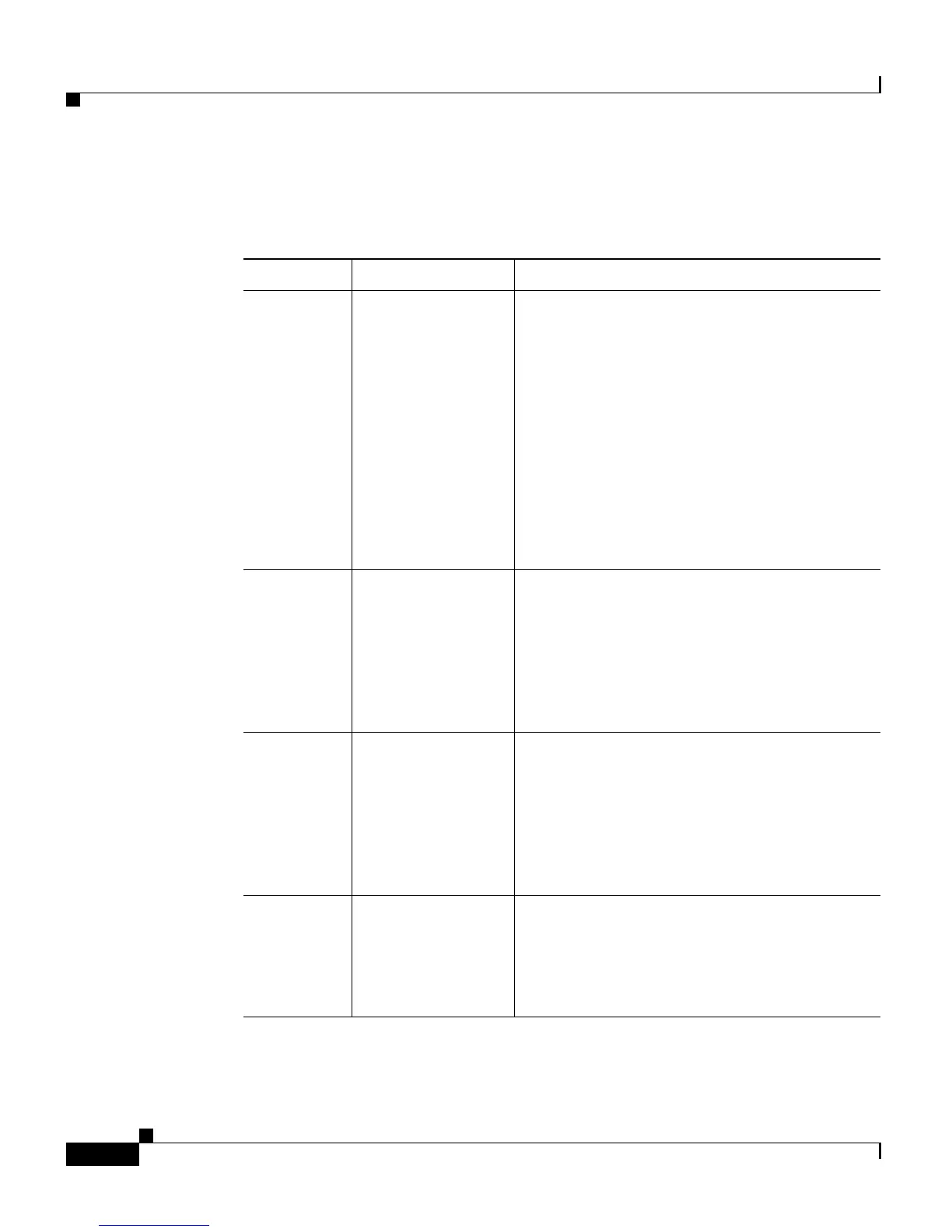
Table 1-1 describes LED functions.
Ta b l e 1-1 LED Functions
LED Color or State Description
STATUS
Green
Red
Flashing
Yellow
Off
At startup, the switch performs a series of
diagnostic tests:
All tests pass
A test other than an individual port test fails
System boot or diagnostic tests in progress
System is in rommon mode or a power supply
has failed
Switch is disabled
CON Green
Off
10/100 BASE-T console port is in link-up
state
10/100 BASE-T console port is in link-down
state or not connected
There are no blinking, red, or yellow states
for this port
MGT Green
Off
10/100 BASE-T Management port is in
link-up state
10/100 BASE-T Management port is in
link-down state or not connected
There are no blinking, red, or yellow states
for this port
Port 1-48 Green
Yellow
Flashing yellow
Off
Port is operational
Port is disabled by user
Power-on self-test indicates faulty port
No signal detected or link configuration
failure
 Loading...