10
To configure 40G ports to function as 10G ports, you need to use Cisco QSFP to four SFP+ Active Optical Breakout Cables that connect a 40G QSFP port of
the switch on one end to four 10G SFP+ ports of the switch on the other end.
Power Supply Slots
The chassis has two power supply slots that accept either AC-input or DC-input power supplies, or one of
each. The chassis is delivered with power supplies pre-installed in the power supply slots. If only one power
supply is ordered, then a blank cover is installed in the empty power supply slot, which must remain installed
if a power supply is not installed.
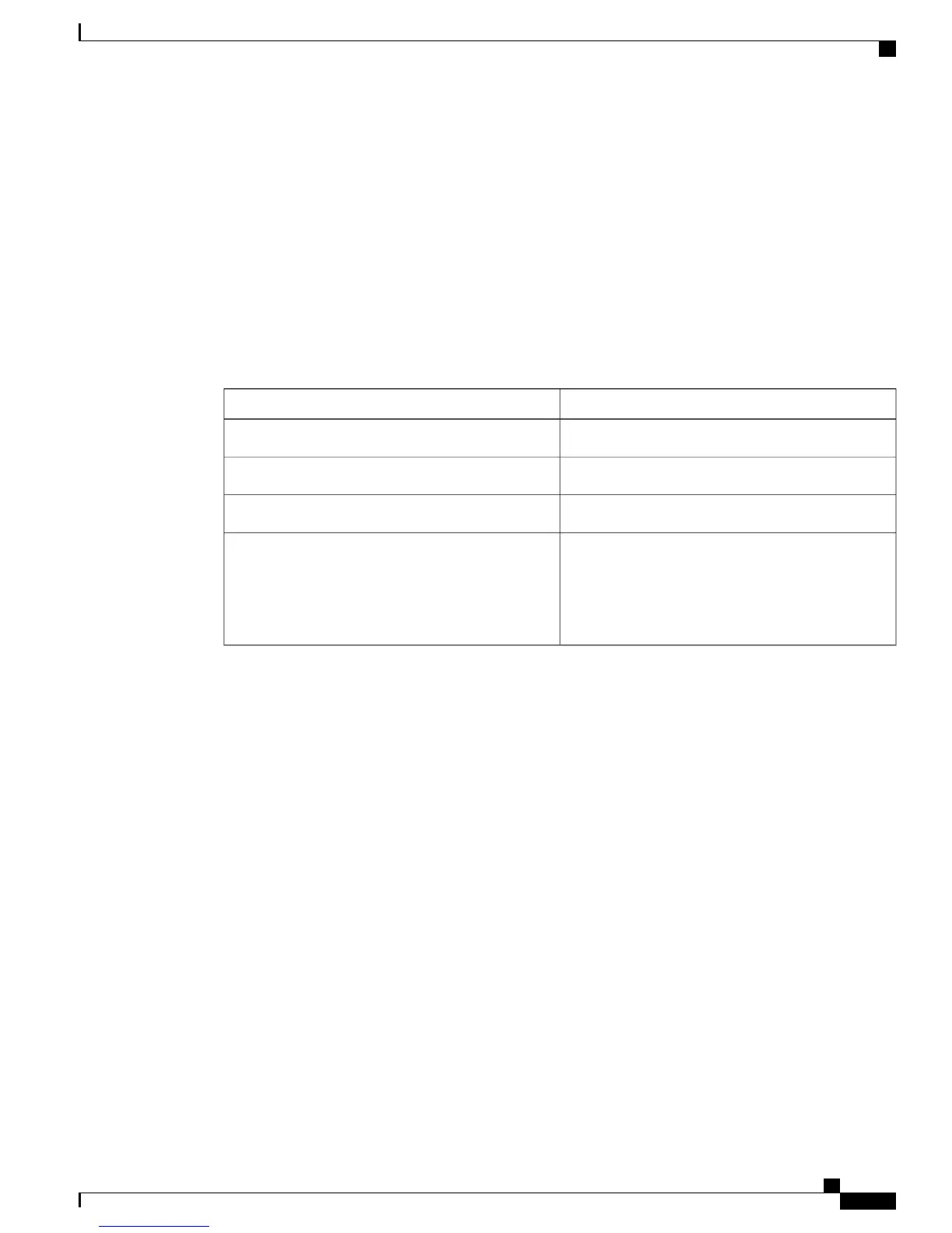
Table 6: Power supplies supported by the switches
Power SupplySwitch
750W and 1100WCatalyst 6816-X-LE
750W and 1100WCatalyst 6832-X-LE
750W and 1100WCatalyst 6824-X-LE-40G
1100W
If you insert a 750W power supply in to the
power supply slot of a Catalyst
6840-X-LE-40G switch, the switch fails to
boot.
Note
Catalyst 6840-X-LE-40G
Related Topics
Front Panel Components
Management Port
The management port is a 10/100/1000 copper Ethernet port directly connected to the route processor. The
switch also has a fibre port that can be used as the Ethernet Management port. It supports TFTP image
downloading, network management, SNMP, Telnet, and SSH connections. The management port is isolated
from other ports in the system in a dedicated management VRF; it is not part of the EARL forwarding logic.
The management port provides direct access to the CPU, even when the system is heavily loaded.
The management port is a Layer 3 port in host mode, and only accepts traffic that terminates on the router.
This port does not route packets between itself and other ports. The port processes only the following packet
types and properly enqueues them:
•
Address Resolution Protocol (ARP)
•
IPv4 unicast
•
IPv6 unicast
•
Cisco Discovery Protocol (CDP)
Catalyst 6840-X Switch Series Hardware Installation Guide
13
Product Overview
Power Supply Slots