• Grounding lug—A two-hole standard barrel lug. Supports up to 8-24 AWG wire. Supplied as part of
accessory kit.
• Grounding screws—Two M4 x 8 mm (metric) pan-head screws. Supplied as part of the accessory kit.
• Grounding wire—Not supplied as part of accessory kit. The grounding wire should be sized according
to local and national installation requirements. Depending on the power supply and system, a 12 AWG
to 6 AWG copper conductor is required for U.S. installations. 8-24 AWG wire is recommended. The
length of the grounding wire depends on the proximity of the switch to proper grounding facilities.
• No. 1 Phillips screwdriver.
• Crimping tool to crimp the grounding wire to the grounding lug.
• Wire-stripping tool to remove the insulation from the grounding wire.
Connecting the System Ground
To establish an earth ground for the chassis, you must attach a grounding cable from the chassis’ grounding
lug to the rack.
Before you begin
Review the following illustration and table.
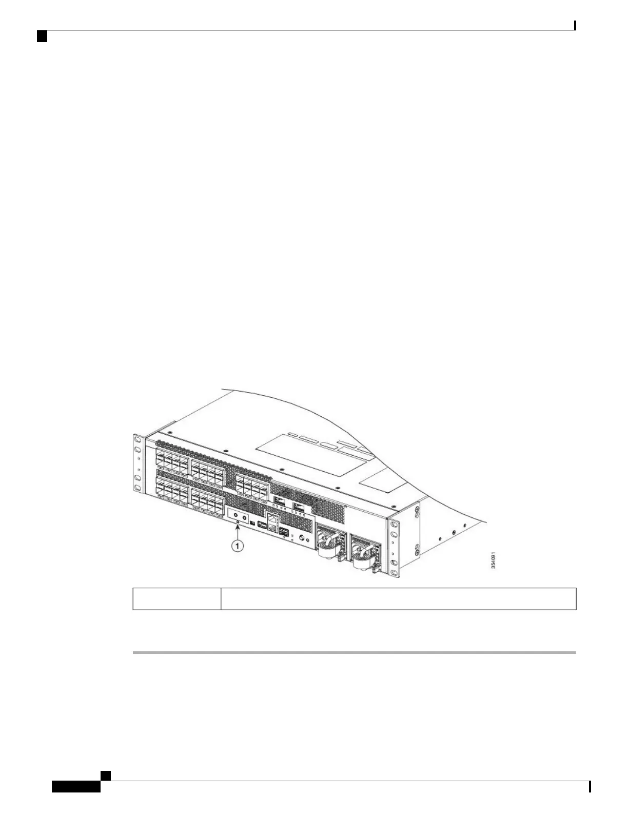
Figure 22: System Ground Location
Location of system ground lug1
Procedure
Step 1 Use a wire-stripping tool to remove approximately 0.75 inch (19 mm) of the covering from the end of the
grounding wire.
Step 2 Insert the stripped end of the grounding wire into the open end of the grounding lug.
Catalyst 6840-X Switch Series Hardware Installation Guide
46
Installing the Switch
Connecting the System Ground