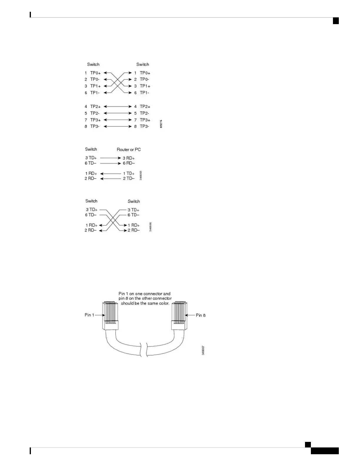
Figure 35: Four Twisted-Pair Semi-Cross Cable Schematic
Figure 36: Two Twisted-Pair Straight-Through Cable Schematic
Figure 37: Two Twisted-Pair Crossover Cable Schematic
Identifying a Crossover Cable
To identify a crossover cable, compare the two modular ends of the cable. Hold the cable ends side-by-side,
with the tab at the back. The wire connected to the pin on the outside of the left plug should be a different
color from the wire connected to the pin on the inside of the right plug.
Figure 38: Identifying a Crossover Cable
Console Port Adapter Pinouts
The RS-232 console port uses an 8-pin RJ-45 connector. Use an RJ-45-to-DB-9 adapter cable to connect the
switch console port to a console PC. You need to provide a RJ-45-to-DB-25 female DTE adapter to connect
the switch console port to a terminal.
Catalyst 6840-X Switch Series Hardware Installation Guide
73
Module Connectors and Cable Specifications
Console Port Adapter Pinouts