The guide pin on the top, right-hand corner of a switching module is designed to slide into compatible slots
only. So the guide pin on a switching module will not slide in all the way if you insert it into a supervisor
module slot.
Tip
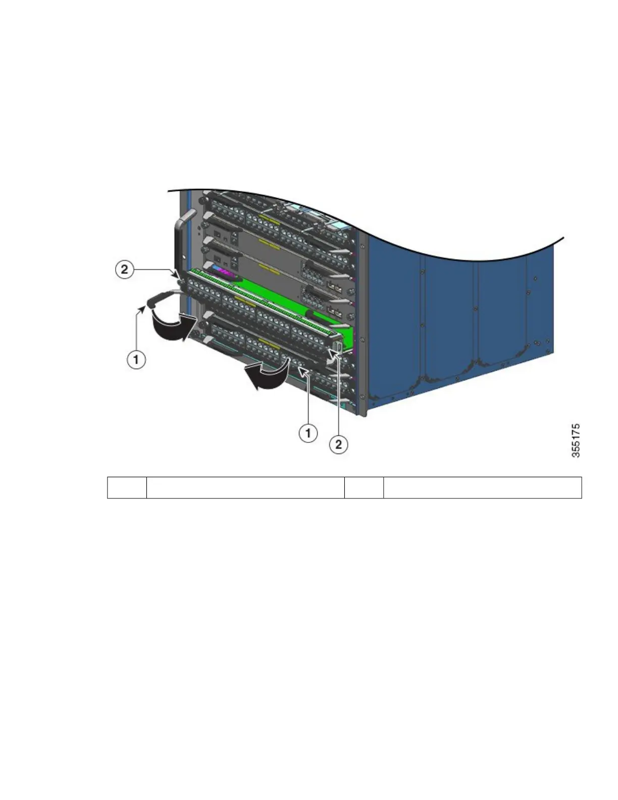
Step 9 Using your thumb and forefinger of each hand, simultaneously pivot in both ejector levers, to fully seat the module in
the backplane connector.
Captive installation screws that must be tightened2Ejector levers that must be pivoted in1
Always use the ejector levers when installing or removing modules. A module that is only partially seated
in the backplane causes the system to halt or subsequently crash. Further, an improperly seated module may
also prevent the system from booting properly.
Caution
If you perform a hot swap, the console displays the message Module <n> has been inserted.. This message
also appears if you are connected to the switch through a Telnet session.
Note
Step 10 Use a screwdriver to tighten the captive installation screw on each end of the module faceplate.
Step 11 Install any necessary transceivers in the module ports.
Installation instructions along with safety warnings for the various types of transceivers can be found at the following
URL: https://www.cisco.com/en/US/products/hw/modules/ps5455/prod_installation_guides_list.html
Step 12 Attach any necessary network interface cables or other devices to the interface ports.
Step 13 Check the status of the module as follows:
a) Ensure that the STATUS LED is green (module operational).
27
 Loading...


