EasyManuals Logo

Cisco Catalyst 9800-L User Manual

Cisco Catalyst 9800-L
14 pages
To Next Page IconTo Next Page
To Previous Page IconTo Previous Page
Page #8 background imageLoading...
Page #8 background image
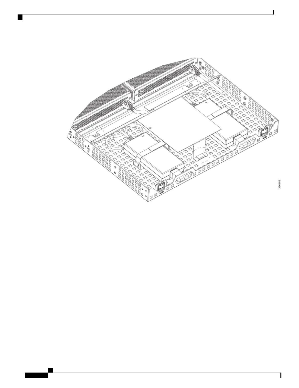
Figure 6: Power Supply Baffle
Step 4 Place the power adapters between either of the two tabs in the rear of the tray and use the provided velcro
straps to secure them.
Step 5 Route the AC wiring through the cable management clips.
Step 6 Re-install and secure tabs on power supply baffle, coil extra cables, and locate them under the baffle.
This is an hot air baffle.
Note
Step 7 Attach the rack mount tray to the rack using the supplied screws and brackets, as shown in figures below:
Installing the Cisco Catalyst 9800-L Wireless Controller
8
Installing the Cisco Catalyst 9800-L Wireless Controller
Rack Mounting the Controller

Questions and Answers:

Question and Answer IconNeed help?

Do you have a question about the Cisco Catalyst 9800-L and is the answer not in the manual?

Cisco Catalyst 9800-L Specifications

General IconGeneral
ModelCisco Catalyst 9800-L
CategoryController
Throughput5 Gbps
RedundancyYes
Max Access Points200
Product TypeWireless LAN Controller
Form FactorRack-mountable
Rack Height1U
USB Ports1x USB 3.0
Redundant Power SupplyOptional
Product FamilyCisco Catalyst 9800 Series
Operating SystemCisco IOS XE
Power SupplyAC power supply
Wireless Standard802.11ax
Management Port1 x RJ-45
InterfaceGigabit Ethernet
EncryptionAES

Related product manuals