Management Port
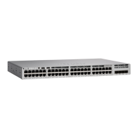
The Ethernet management port, also referred to as the Gi0/0 or GigabitEthernet0/0 port, is a VRF (VPN
routing/forwarding) interface to which you can connect a PC. It supports TFTP image downloading, network
management, SNMP, Telnet, and SSH connections. The switches support out-of-band management through
the Mgmt-vrf. Mgmt-vrf is used to segment management traffic from the global routing table of the switch.
The Ethernet management port supports speeds upto 10/100/1000 Mbps and is set to auto-negotiate.
USB Host Ports
USB host ports lets you connect different USB devices such as flash drives to the switch. USB 2.0 port supports
Cisco USB flash drives with capacities from 128 MB to 8 GB (USB devices with port densities of 128 MB,
256 MB, 1 GB, 4 GB, and 8 GB are supported). The USB 3.0 port provides support for Cisco USB flash
drives with capacities from 64 MB to 16 GB. Cisco IOS software provides standard file system access to the
flash device: read, write, erase, and copy, as well as the ability to format the flash device with a FAT file
system.
The USB host ports are located on different sides of the switches as follows:
• Cisco Catalyst 9500 Series Switches: USB 2.0 port on the front panel and USB 3.0 port on the rear panel.
• Cisco Catalyst 9500 Series High Performance Switches: USB 3.0 port on the front panel.
Mode Button
The mode button has the following function:
• Blue Beacon Mode — works with blue beacon LED to indicate that the switch needs attention
• 10G Status LED Mode — works with 10G Status LEDs to indicate status of 10G ports
Blue Beacon Mode
The blue beacon mode has higher priority over the 10G status LED mode and reset mode. The blue beacon
LED can be provisioned by the operator to indicate that the switch needs attention.
10G Status LED Mode
Each 40G port can be configured to function as a 10G port using a Cisco QSFP to four SFP Active Optical
Breakout Cables that connect a 40G QSFP port of the switch on one end to four 10G SFP ports of the switch
on the other end. After system bootup, the four 10G Status LEDs indicate the status of 10G ports 1-4 by default
which maps to 40G port number 1. A short press on the mode button moves the pointer to the next 10G group
(5-8) which maps to 40G port number 2. You can check the status of all the 96 10G ports by pressing the
mode button 24 times, after which it rolls back to 10G port 1-4.
Network Modules
The C9500-16X and C9500-40X switch models support two network modules that provide uplink ports to
connect to other devices. The switch should only be operated with either a network module or a blank module
installed.
Cisco Catalyst 9500 Series Switches Hardware Installation Guide
18
Product Overview
Management Port
 Loading...


