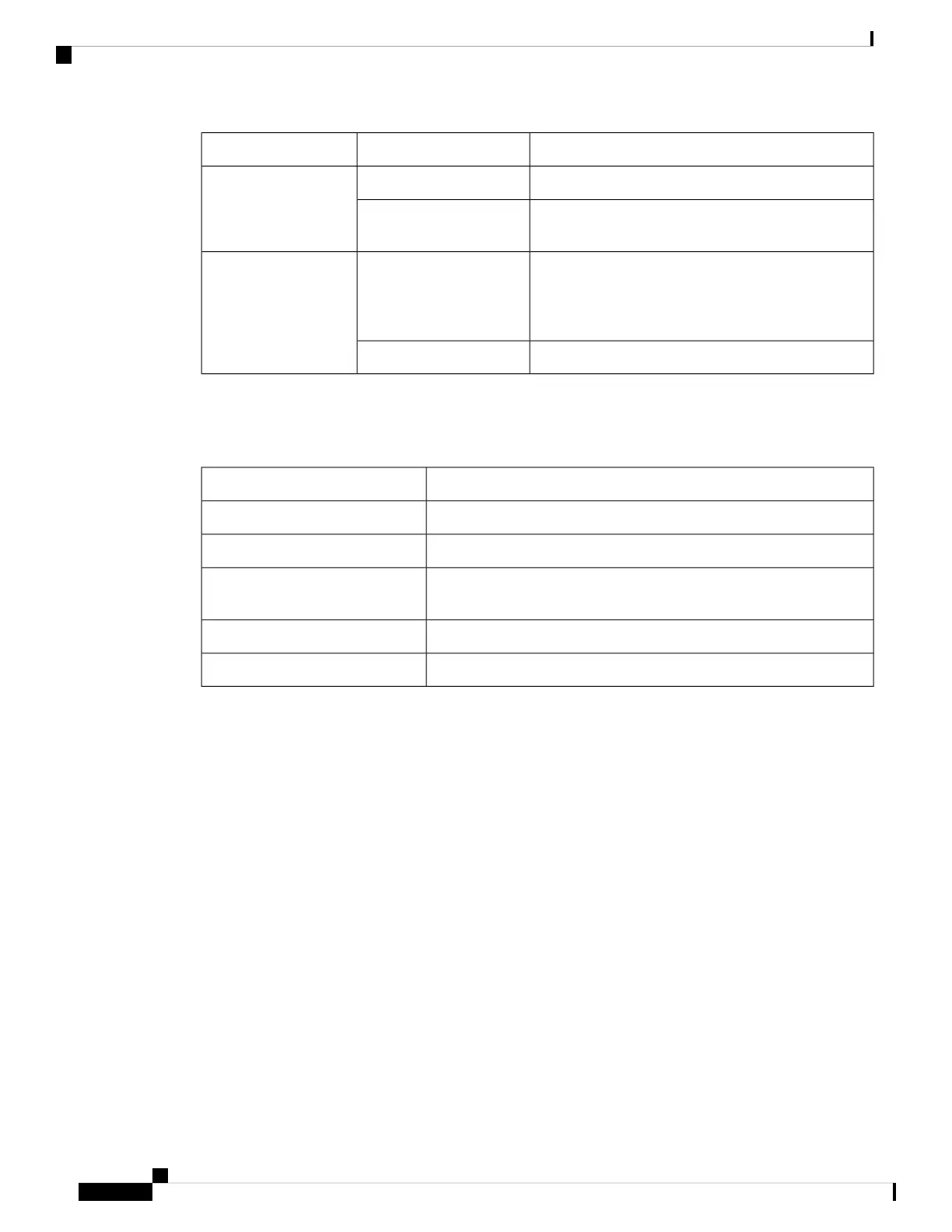
DescriptionStatusLED
12V aux output is on; 12V main output is off.BlinkingGreen
Both 12V aux output and 12V main output are on;
Power supply is functioning normally.
Solid
Warning detected.
OR
AC power cord is not inserted properly.
BlinkingAmber
Critical error detected.Solid
The 1600W AC and DC power supply modules have a bi-color (green/amber) LED to indicate the status of
the power supplies.
Table 15: LEDs on the 1600W AC/DC power supply modules
DescriptionLED Status
No input power.Off
Critical error detected; PSU 12V main output is off.Solid amber
Both 12V aux output and 12V main output are on; Power supply is
functioning normally.
Solid green
Warning detected; PSU 12V main output is on.1Hz blinking amber
PSU 12V main output is off and 12V aux output is on.2Hz blinking green
Installation Guidelines
• The switch chassis must be installed in a cabinet or rack that is secured to the data center.
• Remove the power supply from its shipping container and remove any packaging.
• You need the following additional tools and equipment:
• Nut driver attachment for number 1 Phillips-head screwdriver or ratchet wrench with torque capability
(used only for DC-input power supplies).
• Grounding wire — Size this wire to meet local and national installation requirements. For U.S.
installations, you must use an 8-14 AWG copper conductor for AC power supply systems. For
installations outside the U.S., consult your local and national electrical codes. The length of the
grounding wire depends on the proximity of the switch to proper grounding facilities.
• The chassis is connected to an earth ground.
• You have receptacles for the power sources within reach of the power supply cables.
Cisco Catalyst 9500 Series Switches Hardware Installation Guide
72
Installing Field Replaceable Units
Installation Guidelines