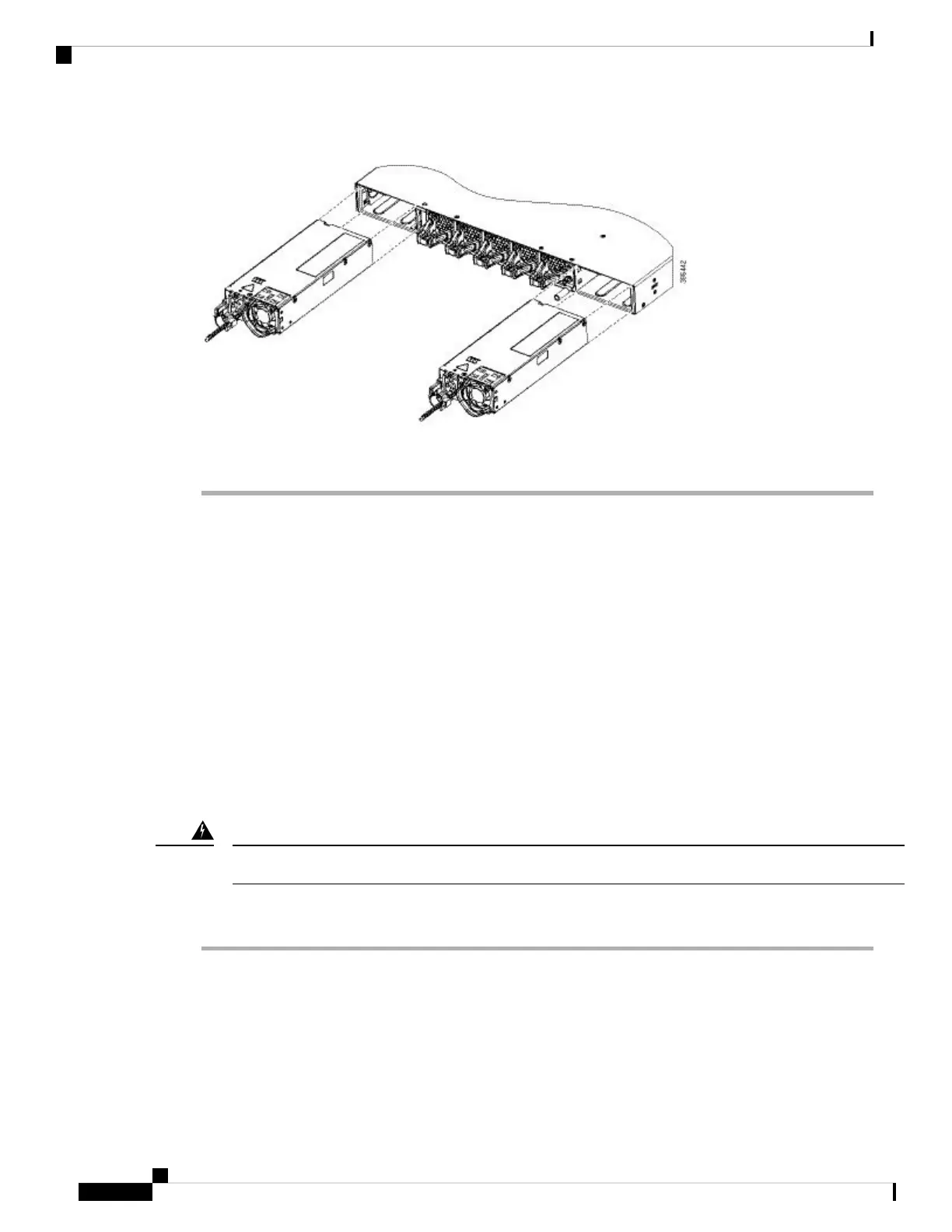
Figure 51: Installing the Power Supply
Connecting to the Power Source
Each power cable is shipped with mating connectors with one of the connectors on the power socket and the
other connector on the front panel of the power supply. You follow the same steps to install the AC-input and
DC-input power supplies, but you must ground them differently.
• AC-input power supply—It is automatically grounded when you connect its power cable to the power
supply and the power source.
• DC-input power supply—You do not connect the power supply directly to the earth ground.
You use one power cord for each power supply to connect the power supply to its power source.
Connecting to an AC Power Source
To connect to a power source, follow these steps:
Take care when connecting units to the supply circuit so that wiring is not overloaded. Statement 1018
Warning
Procedure
Step 1 Prior to connecting the power supply to a power source, ensure that the chassis is properly grounded.
Step 2 Plug the power cable into the power supply.
Step 3 Plug the other end of the power cable into a power source supplied by the data center.
When using redundant mode, connect each power supply to a separate power source.
Note
Cisco Catalyst 9500 Series Switches Hardware Installation Guide
74
Installing Field Replaceable Units
Connecting to the Power Source