DescriptionTask
The various ports on the chassis must be connected
to the network. This process can involve only
attaching a network interface cable to the port or it
can include the installation of a transceiver of some
type in port and then attaching the network interface
cable to the transceiver.
Connector and Cable Specifications
After completing the network cabling and making
sure that system ground is connected, the power
supplies can be turned on. The system powers up and
runs through a set of built-in diagnostics.
Powering up the chassis
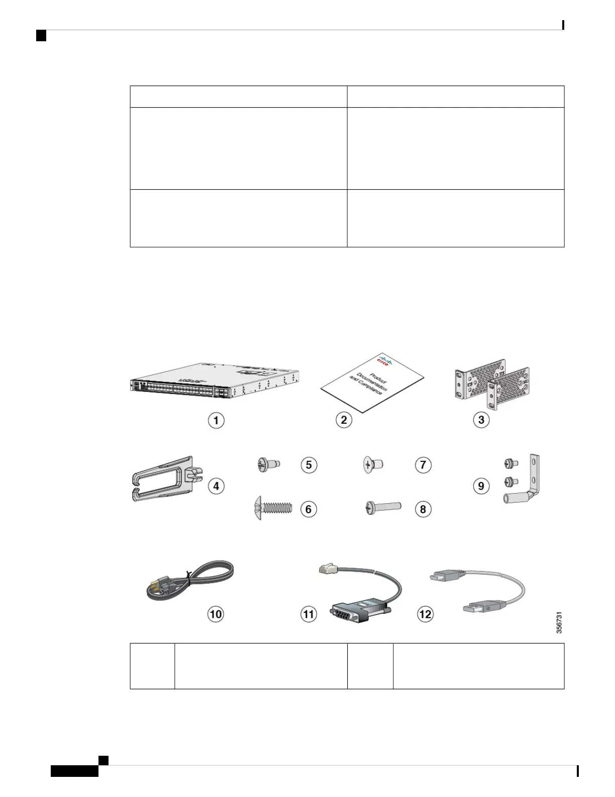
Contents of the Shipping Box
The shipping box contains the model of the switch you ordered and other components needed for installation.
Some components are optional, depending on your order.
Figure 19: Components Delivered in the Shipping Box of Cisco Catalyst 9500 Series Switches
Eight number-8 Phillips flat-head 0.312"
long screws
7Cisco Catalyst 9500 Series switch with
optional network module
1
(power supply
and fan modules not shown)
1
Cisco Catalyst 9500 Series Switches Hardware Installation Guide
36
Installing a Switch
Contents of the Shipping Box