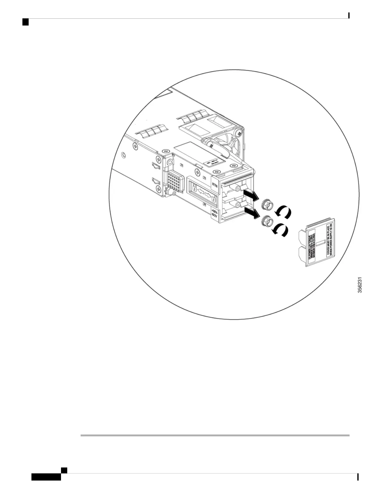
Figure 53: Removing the Nuts on the Terminal Box
c. Secure the positive (+) DC power cable lug to the RTN terminal and the negative (–) DC power cable
lug to the –48V terminal with the nuts.
To tighten the nuts, apply torque between 7 lbf.in (0.8Nm) and 10lbf.in (1.1 Nm) to each nut.
d. Replace the safety cover over the terminal box on the DC power supply.
Step 5 Verify that the power supply is receiving power by checking that the LED is on and is amber or red. For more
information about the power supply LEDs and the conditions that they indicate, see Power Supply LEDs.
When you first activate the power supply, you can verify the functionality of the LED by checking that LED
turns on for a couple of seconds. If the LED is flashing amber or red, check the power connections on the
power supply and the power source.
Cisco Catalyst 9500 Series Switches Hardware Installation Guide
78
Installing Field Replaceable Units
Connecting to a DC Power Source