A-11
User Guide for the Catalyst Express 520 Switches
OL-12761-02
Appendix A Reference
Cabling Guidelines
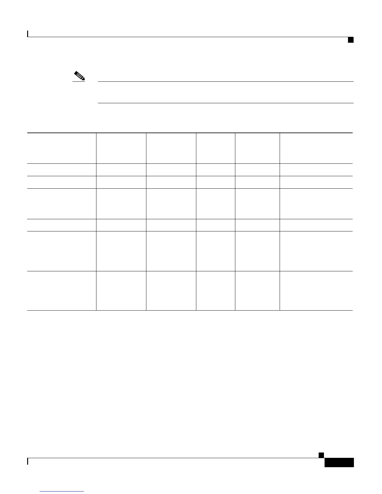
Note When using shorter distances of single-mode fiber cable, you might need to insert
an inline optical attenuator in the link to avoid overloading the receiver.
Table A-2 Fiber-Optic SFP-Module Port Cabling Specifications
SFP Module
Wavelength
(nanometers) Fiber Type
Core Size
(micron)
Modal
Bandwidth
(MHz/km) Cable Distance
100BASE-BX-10D 1550 SMF G.652
2
— 32,810 ft (10 km)
100BASE-BX-10U 1310 SMF G.652
2
— 32,810 ft (10 km)
100BASE-FX-FE
100BASE-FX-GE
Min.: 1270
Typical: 1300
Max.: 1380
MMF 50/125
62.5/125
500 6,562 feet (2 km)
100BASE-LX 1310 SMF G.652
2
— 32,810 ft (10 km)
1000BASE-LX/LH 1300 MMF
1
SMF
1. A mode-conditioning patch cable is required. Using an ordinary patch cable with MMF, 1000BASE-LX/LH SFP modules,
and a short link distance can cause transceiver saturation, resulting in an elevated bit error rate (BER). When using the LX/LH
SFP module with 62.5-micron diameter MMF, you must also install a mode-conditioning patch cable between the SFP
module and the MMF cable on both the sending and receiving ends of the link. The mode-conditioning patch cable is required
for link distances greater than 984 feet (300 m).
62.5
50
50
9/10
500
400
500
—
1804 feet (550 m)
1804 feet (550 m)
1804 feet (550 m)
32,810 feet (10 km)
1000BASE-SX 850 MMF 62.5
62.5
50
50
160
200
400
500
722 feet (220 m)
902 feet (275 m)
1640 feet (500 m)
1804 feet (550 m)