Wall Mount an 8 Port Switch
To wall-mount a 8-port switch using mounting screws, follow these steps:
Step 1 Locate the screw template. The template is used to align the mounting screw holes.
Step 2 Position the screw template so that the edge that is marked as CABLE SIDE ENTRY faces toward the floor. Make sure
that the switch is attached securely to wall studs or to a firmly attached plywoodmounting backboard.
Step 3 Peel the adhesive strip off the bottom of the screw template.
Step 4 Attach the screw template to the wall.
Step 5 Use a 0.144-inch (3.7 mm) or a #27 drill bit to drill a 1/2-inch (12.7 mm) hole in the two screw template slots.
Step 6 Insert two screws in the slots on the screw template, and tighten them until they touch the top of the screw template.
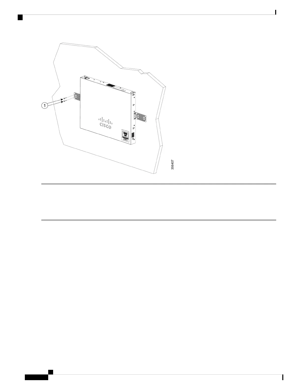
Installing the mounting screws on the wall
Figure 3 Installing the mounting screws on the wall
Get to Know Your Switch
4
Get to Know Your Switch
Wall Mount an 8 Port Switch