Step 10
Reattach the inlet grille screen (see the above figure) to the frame assembly by aligning the four captive screws on the
screen to the screw holes on the frame assembly and tightening the screws with the screwdriver.
Step 11
Attach the lower grille to the chassis by carefully inserting the tabs on the grille into the hook hanger brackets. See the
figure below.
Step 12
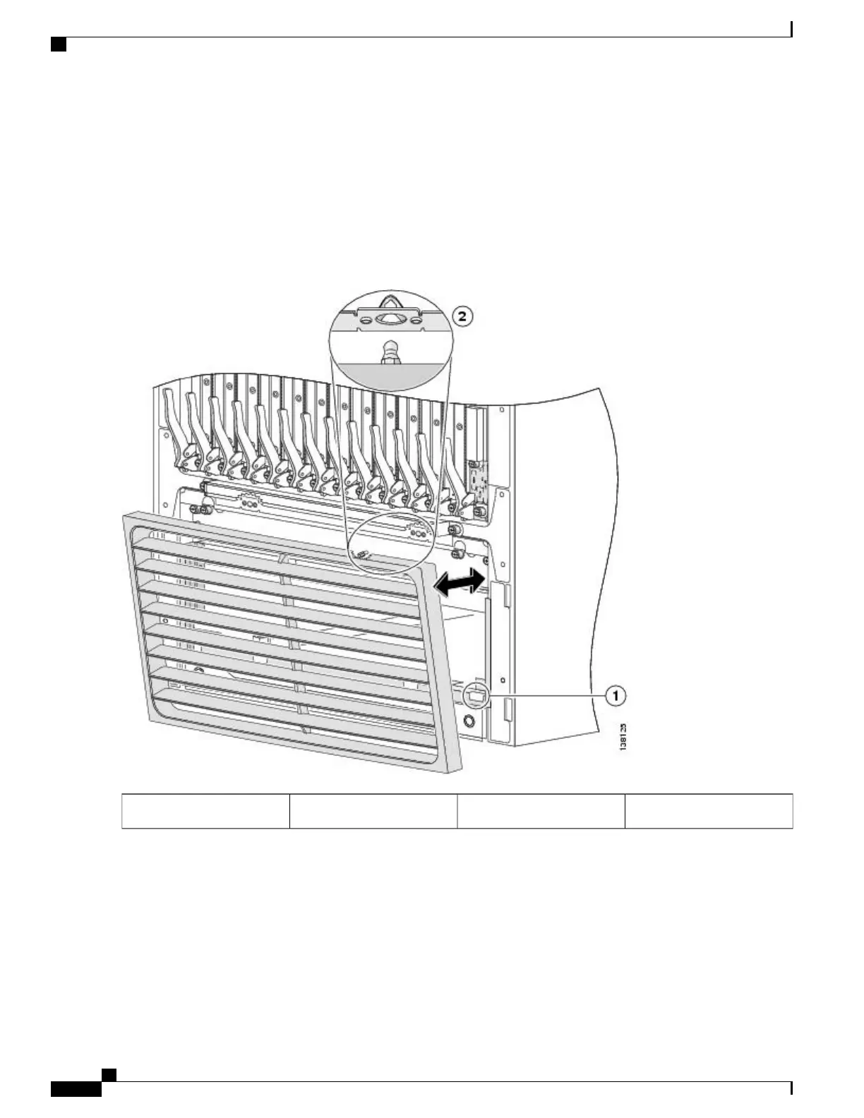
Press the lower grille firmly until it snaps onto the ball stud snaps. See the figure below.
Figure 8: Installing the Lower Grille
Ball stud2Hook hanger brackets1
Step 13
Orient the doors so that the keyhole slots are pointing upwards.
Step 14
Align the doors vertically in their appropriate positions so you can determine where to thread the first two screws that
are adjacent to the keyholes. See the figure below. Set the doors aside, and thread the two screws.
Cisco CRS Carrier Routing System Fabric Card Chassis Installation Guide
12
Installing and Removing Exterior Cosmetic Components
Steps

 Loading...


