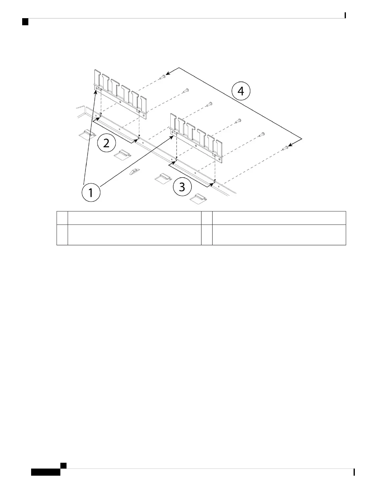
Figure 4: Attach the Cable Guides to the Sliding-Rack Tray Flange
Left cable guide rack tray cutouts2Two cable guides (part number 700-122664-01)1
Six Phillips M3 x 0.5 x 10 mm screws (part number
48-0796-01)
4Right cable guide rack tray cutouts3
a) Align the cable guides with the cutouts on the sliding-rack tray flange (see figure above).
b) At the rear of the sliding-rack tray, attach the left and right cable guides using the six Phillips M3 x 0.5 x 10 mm
screws (part number 48-0796-01).
Drive the screws in while facing the back of the sliding-rack tray.
Note
c) Set the sliding-rack tray aside. Continue with Step 2 to install the rack shelf on the chassis.
The figure in Step 8 shows the sliding rack tray with the cable guides attached.
Step 2 Place the chassis with the top facing down on a large, stable work area.
Step 3 Invert the rack shelf and position it on the chassis. You can mount the chassis with the front or rear panel facing front.
Mount the Chassis
6
Mount the Chassis
Rack-Mount the Chassis
 Loading...


