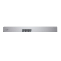
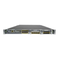
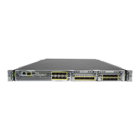
Do not mount the chassis with the rear panel facing downward. This orientation is not supported.
Caution
Step 9 To uninstall the chassis from the wall mount, slide the wall-mounted chassis from the wall, and remove the three screws
from the bottom of the chassis.
What to do next
If you are installing a FIPS cover on the chassis, follow the steps in Install the FIPS Opacity Shield.
Install the cables according to your default software configuration as described in the Cisco Firepower 1010
Getting Started Guide.
Rack-Mount the Chassis
The rack-shelf kit (part number 800-107605-01) contains the following items:
There are two sets of four screws that you can use to secure the chassis to your rack. Chose the screws that
fit your rack.
Note
• Rack shelf (part number 700-122662-01)
• Sliding rack tray (part number 800-107648-01)
• Two cable guides (part number 700-122664-01)
• Six Phillips M3 x 0.5 x 10 mm screws (part number 48-0796-01); use these screws to install the cable
guides.
• Six Phillips M3 x 6 mm screws (part number 48-0384-01); use these screws to secure the rack shelf onto
the chassis.
• Four Phillips 12-24 x 0.75 inch screws (part number 48-0440-01); use these screws to secure the
sliding-rack tray to your rack.
• Four Phillips 10-32 x 0.75 inch screws (part number 48-0441-01); use these screws to secure the
sliding-rack tray to your rack.
Step 1 Install the cable guides on the sliding rack tray:
Mount the Chassis
5
Mount the Chassis
Rack-Mount the Chassis
 Loading...


