Statement 1005—Circuit Breaker
This product relies on the building's installation for short-circuit (overcurrent) protection. To reduce
risk of electric shock or fire, ensure that the protective device is rated not greater than: 20 A, 120 V, and
16 A, 250 V
Warning
Statement 1015—Battery Handling
To reduce risk of fire, explosion or leakage of flammable liquid or gas:
• Replace the battery only with the same or equivalent type recommended by the manufacturer.
• Do not dismantle, crush, puncture, use a sharp tool to remove, short external contacts, or dispose
of the battery in fire.
• Do not use if battery is warped or swollen.
• Do not store or use battery in a temperature > 60° C.
Warning
Statement 1017—Restricted Area
This unit is intended for installation in restricted access areas. Only skilled, instructed, or qualified
personnel can access a restricted access area.
Warning
Statement 1021—SELV Circuit
To avoid electric shock, do not connect SELV circuits to telephone-network voltage (TNV) circuits.
LAN ports contain SELV circuits, and WAN ports contain TNV circuits. Some LAN and WAN ports
both use RJ-45 connectors. Use caution when connecting cables.
Warning
Statement 1024—Ground Conductor
This equipment must be grounded. To reduce the risk of electric shock, never defeat the ground conductor
or operate the equipment in the absence of a suitably installed ground conductor. Contact the appropriate
electrical inspection authority or an electrician if you are uncertain that suitable grounding is available.
Warning
Statement 1029—Blank Faceplates and Cover Panels
Blank faceplates and cover panels serve three important functions: they reduce the risk of electric shock
and fire, they contain electromagnetic interference (EMI) that might disrupt other equipment, and they
direct the flow of cooling air through the chassis. Do not operate the system unless all cards, faceplates,
front covers, and rear covers are in place.
Warning
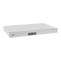
Cisco Firepower 1100 Series Hardware Installation Guide
20
Installation Preparation
Installation Warnings
 Loading...