The rack is a standard Electronic Industries Association (EIA) rack. It is a 4-post-EIA-310-D, which is the
current revision as specified by EIA. The vertical hole spacing alternates at .50 inches (12.70 mm) to .625
inches (15.90 mm) to .625 inches (15.90 mm) and repeats. The start and stop space is in the middle of the
.50-inch holes. The horizontal spacing is 18.312 inches (465.1 mm), and the rack opening is specified as a
minimum of 17.75 inches (450 mm).
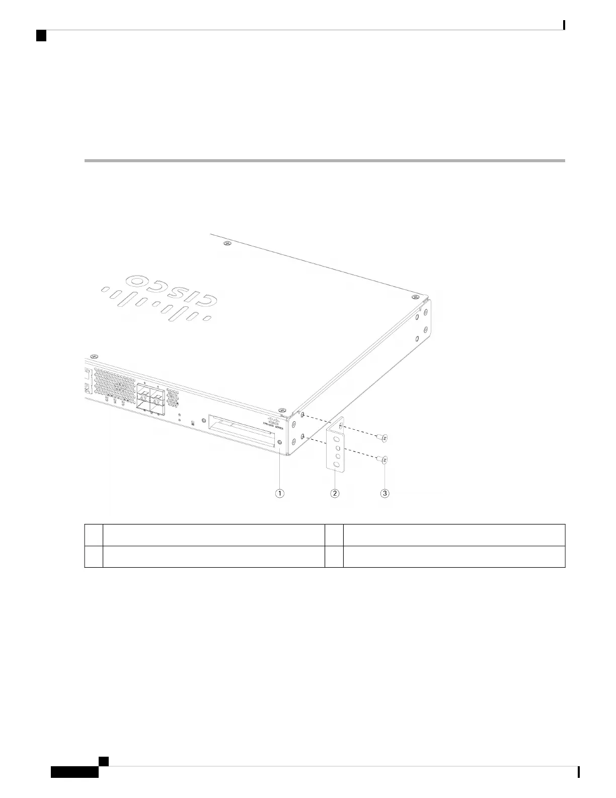
Step 1 Attach both brackets (part number 700-117078-01) to the sides of the chassis using the four M4 x 8-mm Phillips screws
(part number 848-0451-01) that shipped with your chassis. After the brackets are secured to the chassis, you can mount
it in the rack.
Figure 23: Attach Brackets to Chassis
Rack-mount bracket2Chassis back panel1
—M4 x 8-mm Phillips screws (two per side)3
Step 2 Attach the chassis to the rack using the screws that shipped with the chassis.
There are three sets of four screws that you can use to secure the chassis to your rack. Chose the screws that
fit your rack. See Package Contents, on page 5 for the list of rack screws.
Note
We recommend that you install the chassis with the I/O side (rear panel) facing the cold aisle. See the following illustration
for an example of air flow from rear panel (cold aisle) to the front panel (hot aisle).
Cisco Firepower 1100 Series Hardware Installation Guide
26
Rack-Mount the Chassis
Rack-Mount the Chassis
 Loading...