8-32 x 0.375-inch Phillips screws (three per side)3
Step 4 Attach a cable management bracket to each slide rail locking bracket using the four 8-32 x 0.375-inch Phillips screws
provided in the accessory kit.
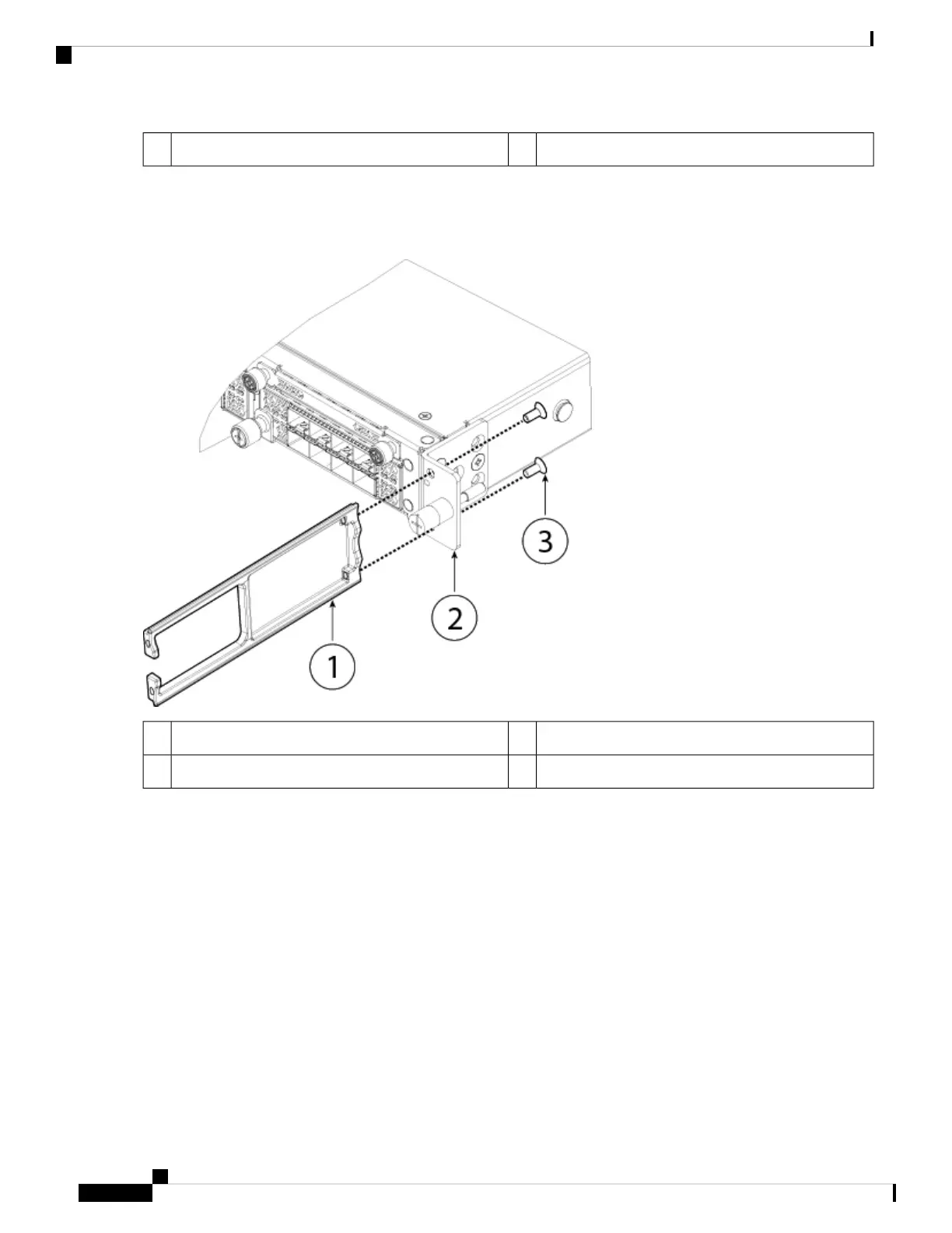
Figure 16: Attach the Cable Management Bracket to the Slide Rail Locking Bracket
Slide rail locking bracket2Cable management bracket1
8-32 x 0.375 inch Phillips screws (two per side)3
Step 5 Connect the cables to the ports. Install the cables according to your default software configuration as described in the
Cisco Firepower 4100 Getting Started Guide. Make sure that the cables have enough slack to route them through the
cable mounting brackets (as shown in Step 6 below).
If you are installing the FIPS opacity shield after the initial product installation, the cables are connected. If
the attached cables do not have enough slack to route them through the cable mounting brackets (as shown
below), you will have to turn the power off on the appliance, remove the cables, route the cables through the
cable mounting brackets, reattach the cables, and continue with Step 7 below.
Note
Step 6 Route the cables through the openings in the cable management brackets.
Installation, Maintenance, and Upgrade
24
Installation, Maintenance, and Upgrade
Install the FIPS Opacity Shield
 Loading...


