Cable the Device (6.4)
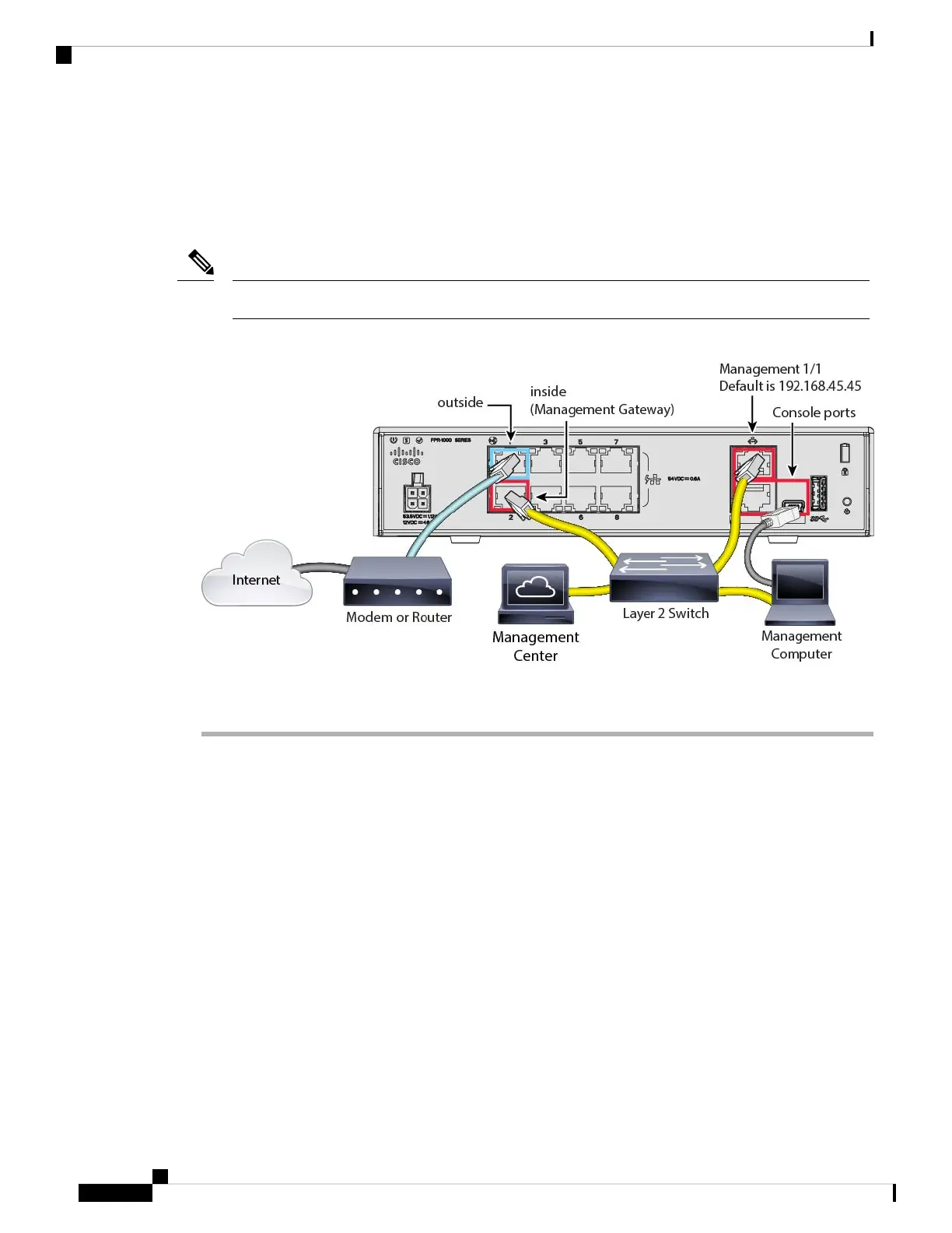
To cable the recommended scenario on the Firepower 1010, see the following illustration, which shows a
sample topology using a Layer 2 switch.
Other topologies can be used, and your deployment will vary depending on your requirements.
Note
Figure 4: Cabling the Firepower 1010
Procedure
Step 1 Install and familiarize yourself with your hardware using the hardware installation guide.
Step 2 Cable the following to a Layer 2 Ethernet switch:
• Inside interface (for example, Ethernet 1/2)
• Management 1/1 interface
• Management Center
• Management computer
The Firepower 1010 and the management center both have the same default management IP address:
192.168.45.45. This guide assumes that you will set different IP addresses for your devices during
initial setup. Note that the management center on 6.5 and later defaults to a DHCP client for the
management interface; however, if there is no DHCP server, it will default to 192.168.45.45.
Note
Step 3 Connect the management computer to the console port. You need to use the console port to access the CLI
for initial setup if you do not use SSH to the Management interface.
Step 4 Connect the outside interface (for example, Ethernet 1/1) to your outside router.
Cisco Firepower 1010 Getting Started Guide
12
Threat Defense Deployment with the Management Center
Cable the Device (6.4)
 Loading...


