Chapter 1
Product Overview
4
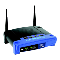
Wireless-N Gigabit Router
apter 1:
ro
uct Overview
hank
ou
or choosing the Links
s Wireless-N Gigabit
Router. The Router lets you access the Internet via a
wireless connection or through one of its four switched
orts. You can a
so use t
e Router to s
are resources, suc
s computers. A variety o
security
eatures help to protect
your data and your privacy while online. Security features
nclude WPA2 securit
, a State
ul Packet Inspection (SPI)
irewall and NAT technology. Con
iguring the Router is
easy using the provided browser-based utility
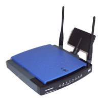
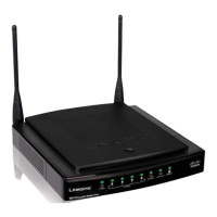
Front Panel
1, 2, 3, 4
Green/Blue)
hese numbered LEDs,
correspon
ing wit
t
e num
ere
ports on t
e
Router’s back panel, serve two purposes. The
LED is solidly lit when the Router is connected
to a device through that port. It
lashes to
ndicates network activity. Green indicates
Gigabit speeds, and blue indicates 10/100
spee
s
Wi-Fi Protected Setup Button
ou have
client devices, such as wireless ada
ters, that
support Wi-Fi Protecte
Setup, t
en
ou can
se Wi-Fi Protecte
Setup to automatica
configure wireless security for your wireless
etwor
(s).
o use Wi-Fi Protected Setup, run the Setup
izard, or refer to the “Wireless > Basic Wireless
ettings” section of “Chapter 3: Advanced
Con
i
uration”.
Wi-Fi Protected Setup LED (Blue/Amber
I
ig
ts up
ue w
en wire
ess securit
is
n
l
Th
LED
l
h
l
r
w
inutes durin
Wi-Fi Protected Setup.
T
e LED
i
ts up am
er i
h
r
i
n
rr
r
durin
the W
Fi Protected Setu
rocess. Make
sure t
e c
ient
evice supports W
Fi Protecte
etup. Wait until the LED is o
, and then tr
again.
The LED flashes amber when a W
i Protecte
etup session is active, an
a secon
session
e
ins. The Router supports one session at a
time. Wait until the LED is off before starting the
ext Wi-Fi Protecte
Setup session
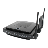
Wireless
B
ue
e Wire
ess LED
ig
ts up
wh
n
h
wir
l
r
i
n
l
I
h
LED
s flashing, the Router is actively sending or
eceiving
ata over t
e networ
Internet
B
ue
T
e Internet LED
ig
ts up
w
en t
ere is a connection ma
e t
rou
t
e
Internet port. A flashin
LED indicates networ
ctivit
over t
e Internet port
Power (Blue
The Power LED li
hts up and will
sta
on w
i
e t
e Router is powere
on. W
en
the Router
oes throu
h its sel
-dia
nostic
ode during every boot-up, this LED will flash.
en t
e
iagnostic is comp
ete, t
e LED wi
e so
i
it
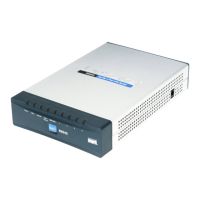
B
c
P
ne
Internet
his Gigabit port is where you will
connect
our ca
e or DSL Internet connection.
1, 2, 3, 4
ese Giga
it ports (1, 2, 3, 4) connect
the Router to com
uters and other Ethernet
etwor
evices on your wire
networ
.
Reset
ere are two wa
s to reset t
e Router’s
actory de
aults. Either press and hold the Reset
Button for approximately five seconds, or restore
the de
aults
rom Administratio
actor
De
aults in the Router’s web-based utility.
Power The Power port is where you will
connect t
e power a
apter
Placement Positions
ere are two wa
s to p
sica
insta
t
e Router. T
e
irst way is to place the Router horizontally on a surface.
e secon
wa
is to mount t
e Router on a wa
Horizonta
P
acement
he Router has four rubber feet on its bottom panel. Place
h
R
r
n
l
v
l
r
n
r
n
l
ri
l
l

 Loading...