6-26
Cisco PIX Firewall Hardware Installation Guide
78-15170-01
Chapter 6 PIX 525
Installing a DC Power Supply
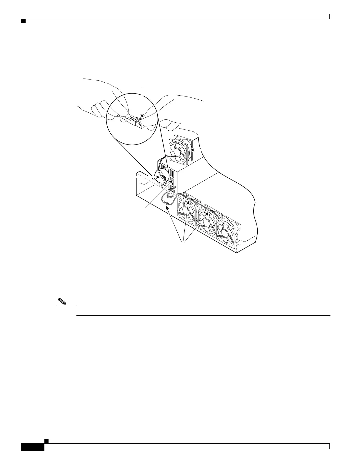
Step 4 Disconnect the fan cable as shown in Figure 6-27, and set the fan aside.
Figure 6-27 Disconnecting the Fan Cable
Step 5
Remove the next fan and disconnect its cable.
Step 6 Remove the cables for the two remaining fans. Remove the last two fans.
Step 7 Replace the fans, starting with the fan farthest away from the power supply. If the bezel is removed, make
sure the fan farthest away from the power supply does not cover the bezel holes.
Note Make sure that the label on the fan faces the chassis wall to ensure proper airflow direction.
Step 8 Install cable clamps onto the fans by aligning cable clamp holes over fan mounting holes and pressing
rivets through both. (See Figure 6-28.)
Depress tab
and pull outward
31106
Fan
Power supply
Location of the three
remaining fan connectors
Fan connector

 Loading...