6-28
Cisco PIX Firewall Hardware Installation Guide
78-15170-01
Chapter 6 PIX 525
Installing a DC Power Supply
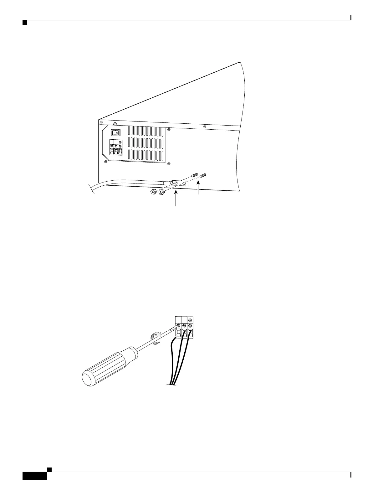
Figure 6-29 Attaching a Grounding Lug to the PIX Firewall
Step 15
Ensure that power is removed from the DC circuit. To ensure that all power is OFF, locate the circuit
breaker on the panel board that services the DC circuit, switch the circuit breaker to the OFF position,
and tape the switch handle of the circuit breaker in the OFF position.
Step 16 Strip the ends of the wires for insertion into the power connect lugs on the PIX 525.
Step 17 Refer to Figure 6-30 and insert the ground wire into the connector for the earth ground and tighten the
screw on the connector. Using the same method as for the ground wire, connect the negative wire and
then the positive wire.
Figure 6-30 Attaching DC Power Cables
11827
Grounding studs on
PIX Firewall DC model
2-hole copper
standard barrel
grounding lug
To rack
ground
10-32 nuts
Rear of
PIX Firewall
+
–
11779
+
–

 Loading...