3-3
Cisco PIX Firewall Hardware Installation Guide
78-15170-01
Chapter 3 PIX 506/506E
PIX 506/506E Product Overview
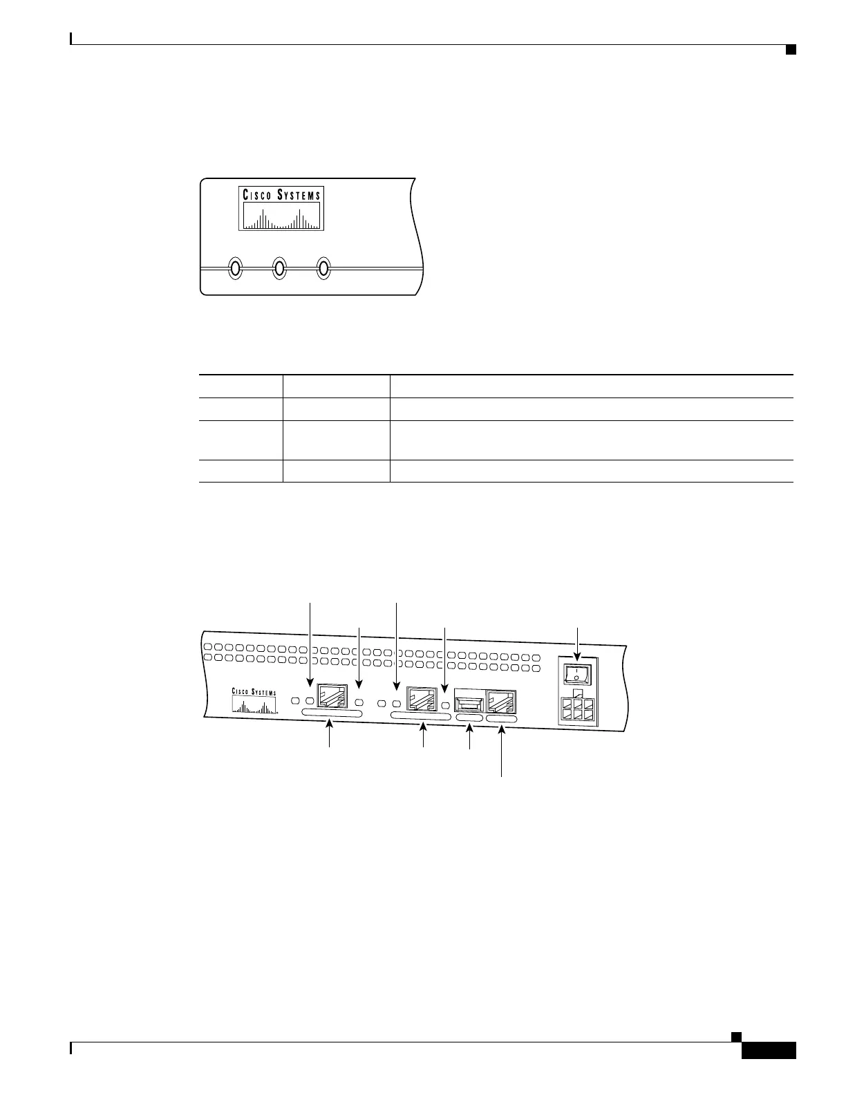
Figure 3-5 shows the PIX 506/506E front panel LEDs.
Figure 3-5 PIX 506/506E Front Panel LEDs
Table 3-1 lists the state of the PIX 506/506E front panel LEDs.
Figure 3-6 shows the PIX 506 rear panel LEDs.
Figure 3-6 PIX 506 Rear Panel LEDs
POWER ACT NETWORK
25735
Table 3-1 PIX 506/506E Front Panel LEDs
LED State Description
POWER On The unit has power.
ACT Flashing green Active indicator—On when the software image has been loaded on
the PIX 506/506E unit.
NETWORK Flashing green On when at least one network interface is passing traffic.
C
O
N
S
O
LE
E
T
H
E
R
N
E
T
0
ACT
LINK
LINK
DC
POWER
INPUT
ACT
U
S
B
E
T
H
E
R
N
E
T
1
38852
10BaseT
(RJ-45)
10BaseT
(RJ-45)
Console
port (RJ-45)
USB
port
Power switch
LINK
LED
LINK
LED
ACT(ivity)
LED
ACT(ivity)
LED

 Loading...