3-6
Cisco PIX Firewall Hardware Installation Guide
78-15170-01
Chapter 3 PIX 506/506E
Connecting a Power Supply Module to the PIX 506/506E
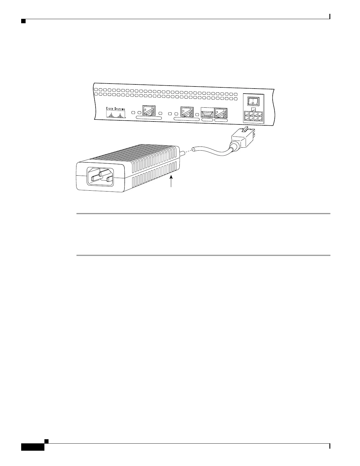
Figure 3-9 displays the cable connection from the power supply to the PIX 506/506E , and displays the
AC power cord connector (at the opposite end of the power supply)
Figure 3-9 Connecting the Power Supply Module to the PIX 506/506E 8 - Pin Connector
Complete these steps to connect the power supply module:
Step 1 Place the PIX 506/506E on a flat, stable surface. The PIX 506/506E is not rack mountable.
Step 2 Connect the power supply to the back of the PIX 506/506E. See Figure 3-8 for the PIX 506 and
Figure 3-9 for the PIX 506E .
Step 3 When you are ready to start the PIX 506/506E, power on the unit from the switch at the rear of the unit.
C
O
N
S
O
L
E
E
T
H
E
R
N
E
T
0
ACT
LINK
LINK
DC
POWER
INPUT
ACT
U
S
B
E
T
H
E
R
N
E
T
1
67847
Power supply

 Loading...