4-18
Cisco PIX Firewall Hardware Installation Guide
78-15170-01
Chapter 4 PIX 515/515E
Installing a Circuit Board in the PIX 515/515E
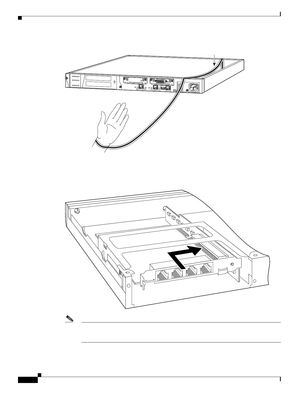
Figure 4-20 Attaching the PIX 515/515E Grounding Strap
Step 2
Remove the screws from the rear assembly on the left and put the assembly aside.
Step 3 Insert a circuit board through the cage opening and into the slot as shown in Figure 4-21.
Figure 4-21 Inserting a Circuit Board into the PIX 515/515E
Note When you insert a four-port Ethernet circuit board in the slot, the end of the circuit board’s
connector extends past the end of the slot. This does not affect the use or operation of the circuit
board.
D
O
N
O
T
I
N
S
T
A
L
L
I
N
T
E
R
F
A
C
E
C
A
R
D
S
W
I
T
H
P
O
W
E
R
A
P
P
L
I
E
D
C
O
N
S
O
L
E
1
0
/1
0
0
E
T
H
E
R
N
E
T
0
/0
L
in
k
F
D
X
F
D
X
1
0
0
M
bp
s
Lin
k
10
0
M
b
p
s
FA
IL
O
V
E
R
1
0
/1
0
0
E
T
H
E
R
N
E
T
0
/0
PIX-515
24304
Copper foil
61904

 Loading...