6-2
Cisco PIX Firewall Hardware Installation Guide
78-15170-01
Chapter 6 PIX 525
PIX 525 Product Overview
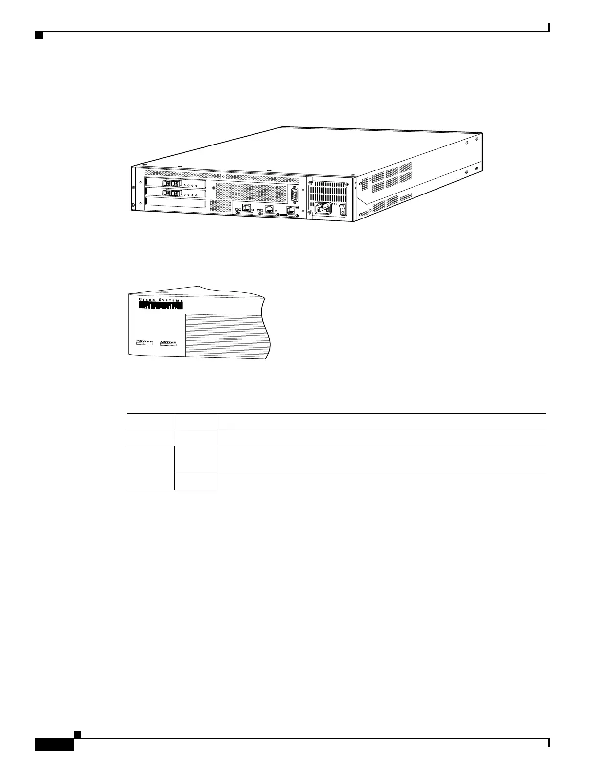
Figure 6-2 shows the rear view of the PIX 525.
Figure 6-2 PIX 525 Rear Panel
There are two LEDs on the front panel of the PIX 525 (see Figure 6-3).
Figure 6-3 PIX 525 Front Panel LEDs
Table 6-1 lists the state of the PIX 525 front panel LEDs.
There are three LEDs for the each RJ-45 interface port and three types of fixed interface connectors on
the back of the PIX 525.
61907
F
A
I
L
O
V
E
R
1
0
0
M
b
p
s
A
C
T
1
0
0
M
b
p
s
A
C
T
L
I
N
K
L
I
N
K
10/100 ETHERNET 1
10/100 E
THE
RN
ET 0
USB
C
ON
SO
LE
P
I
X
-
5
2
5
61913
Table 6-1 PIX 525 Front Panel LEDs
LED Status Description
POWER On On when the unit has power.
ACT On On when the unit is the active failover unit. If failover is present, the light is on
when the unit is the active unit.
Off off when the unit is in standby mode.

 Loading...