6-13
Cisco PIX Firewall Hardware Installation Guide
78-15170-01
Chapter 6 PIX 525
Installing a Memory Upgrade
Remove the component tray and all the screws holding the assembly in place. Refer to “Removing and
Replacing the PIX 525 Chassis Cover” for information on how to remove and replace the top panel.
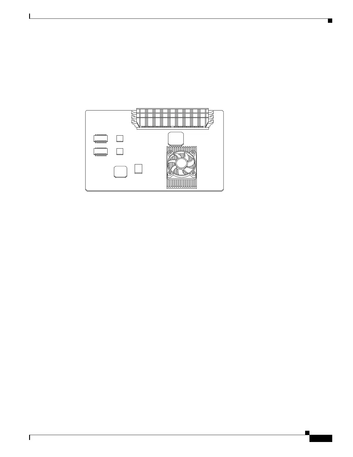
Determine the location of your system memory sockets (see Figure 6-11).
Step 3 Use the markings on the motherboard to determine the socket numbers. Always install the first memory
board into the lowest socket number. Progressively add memory boards into higher numbered sockets.
Figure 6-11 System Memory Location on the PIX 525 Component Tray
Step 4
Locate the wrist grounding strap in the accessory kit and connect one end to the unit or to the
PIX Firewall chassis, and securely attach the other to your wrist so it contacts your bare skin.
Step 5 With the wrist strap on your wrist, carefully grasp the memory strip from either end. Note that a DIMM
strip has notches.
Step 6 To install a DIMM strip:
• Remove the old memory strip by opening the two plastic wing connectors, and pulling the old strip
up. Discard the old strip.
• When installing the memory strip in a PIX 525, install the new strip in Bank 0 as shown in
Figure 6-12 and Figure 6-13, by opening the two plastic wing connectors, inserting the strip, and
closing the wing connectors.
61910

 Loading...