EasyManuals Logo

Cisco PIX 501 Hardware Installation Guide

Cisco PIX 501
140 pages
To Next Page IconTo Next Page
To Previous Page IconTo Previous Page
Page #92 background imageLoading...
Page #92 background image
6-16
Cisco PIX Firewall Hardware Installation Guide
78-15170-01
Chapter 6 PIX 525
Installing a Circuit Board in the PIX 525
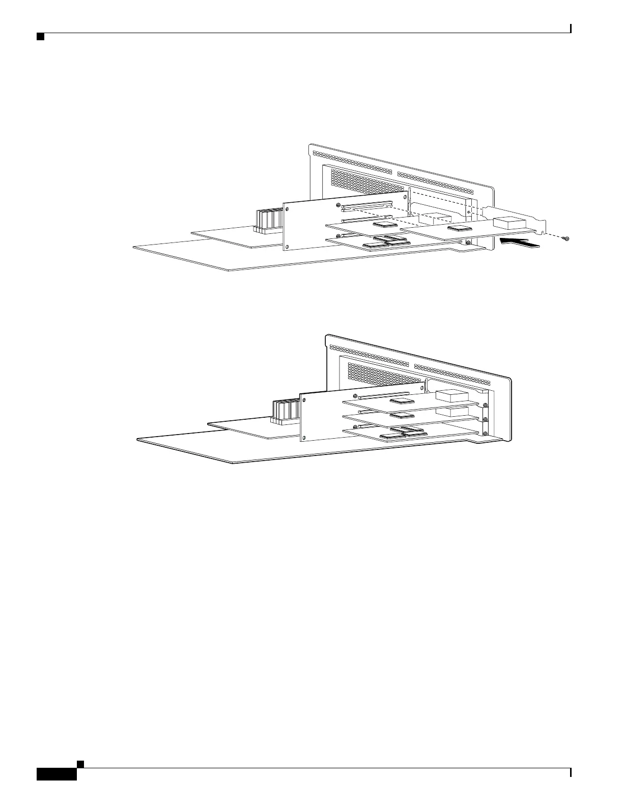
Step 5 Attach the screw to hold the circuit boards connecting flange to the rear cover plate on the component
tray.
Figure 6-15 Inserting an Expansion Board into a PCI Slot on the PIX 525 Component Tray
Step 6 Figure 6-16 shows circuit boards in PCI slots on the component tray.
Figure 6-16 Expansion Boards in PCI Slots on the PIX 525 Component Tray
Step 7
Reinstall the component tray into the PIX 525 chassis.
61911
61909

Table of Contents

Other manuals for Cisco PIX 501

Questions and Answers:

Question and Answer IconNeed help?

Do you have a question about the Cisco PIX 501 and is the answer not in the manual?

Cisco PIX 501 Specifications

General IconGeneral
VPN Throughput3 Mbps
Maximum VPN Peers10
Firewall TypeStateful
Power Supply12V DC
Interfaces4 x 10BASE-T Ethernet

Related product manuals