5-3
Cisco PIX Firewall Hardware Installation Guide
78-15170-01
Chapter 5 PIX 520
PIX 520 Product Overview
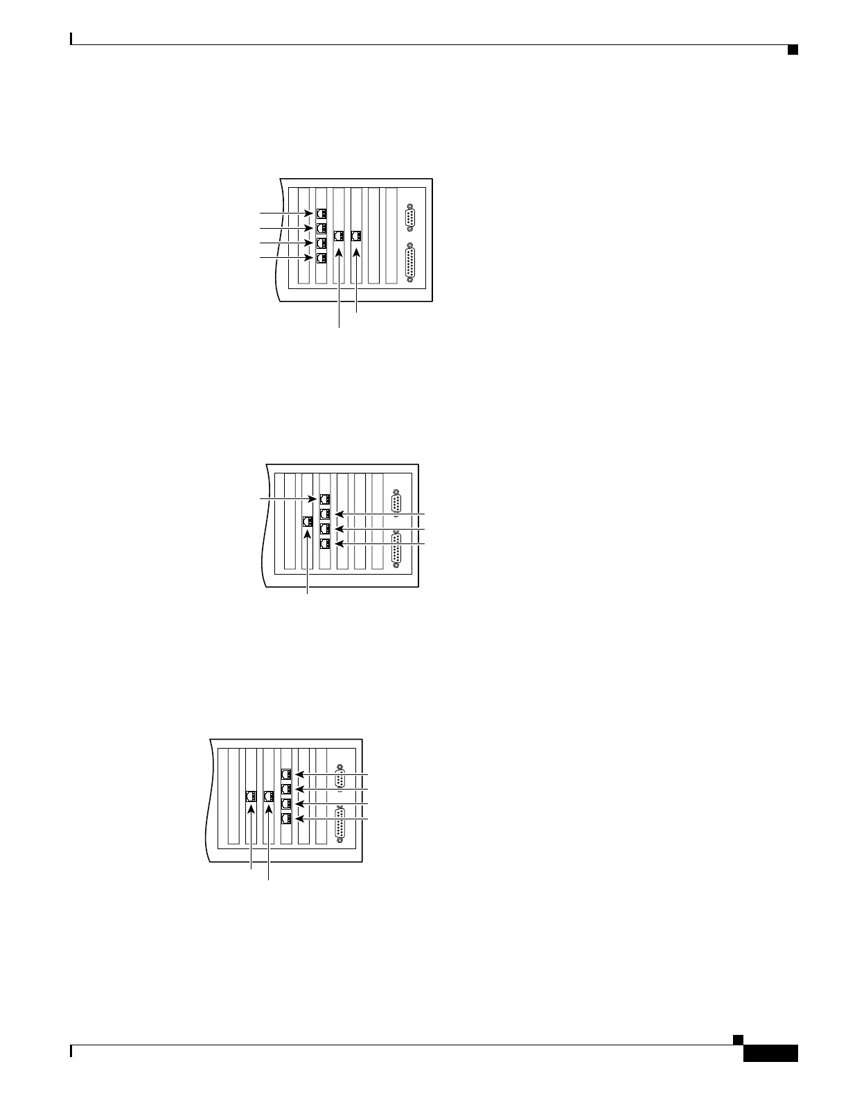
Figure 5-3 shows the location of the interfaces if you install a four-port Ethernet circuit board in slot 0.
Figure 5-3 Four-Port Ethernet Circuit Board Installed in Slot 0
Figure 5-4 shows how the slots are numbered if a single-port Ethernet circuit board is inserted in
slot 0, and a four-port Ethernet circuit board is inserted in slot 1.
Figure 5-4 Single-Port Ethernet Circuit Board Installed in Slot 0 and Four-Port Ethernet Circuit Board
Installed in Slot 1
Figure 5-5 shows how the slots are numbered if single-port Ethernet circuit boards are installed in slot 0
and in slot 1, and a four-port Ethernet circuit board is inserted in slot 2.
Figure 5-5 Single-Port Ethernet Circuit Board Installed in Slot 0 and 1 and Four-Port Ethernet Circuit
Board Installed in Slot 2
44306
Interface 5
Interface 4
Interface 0
Interface 1
Interface 2
Interface 3
44307
Interface 0
Interface 1
Interface 2
Interface 3
Interface 4
44308
Interface 0
Interface 1
Interface 3
Interface 4
Interface 2
Interface 5
 Loading...


