5-16
Cisco PIX Firewall Hardware Installation Guide
78-15170-01
Chapter 5 PIX 520
Installing a Circuit Board in the PIX 520
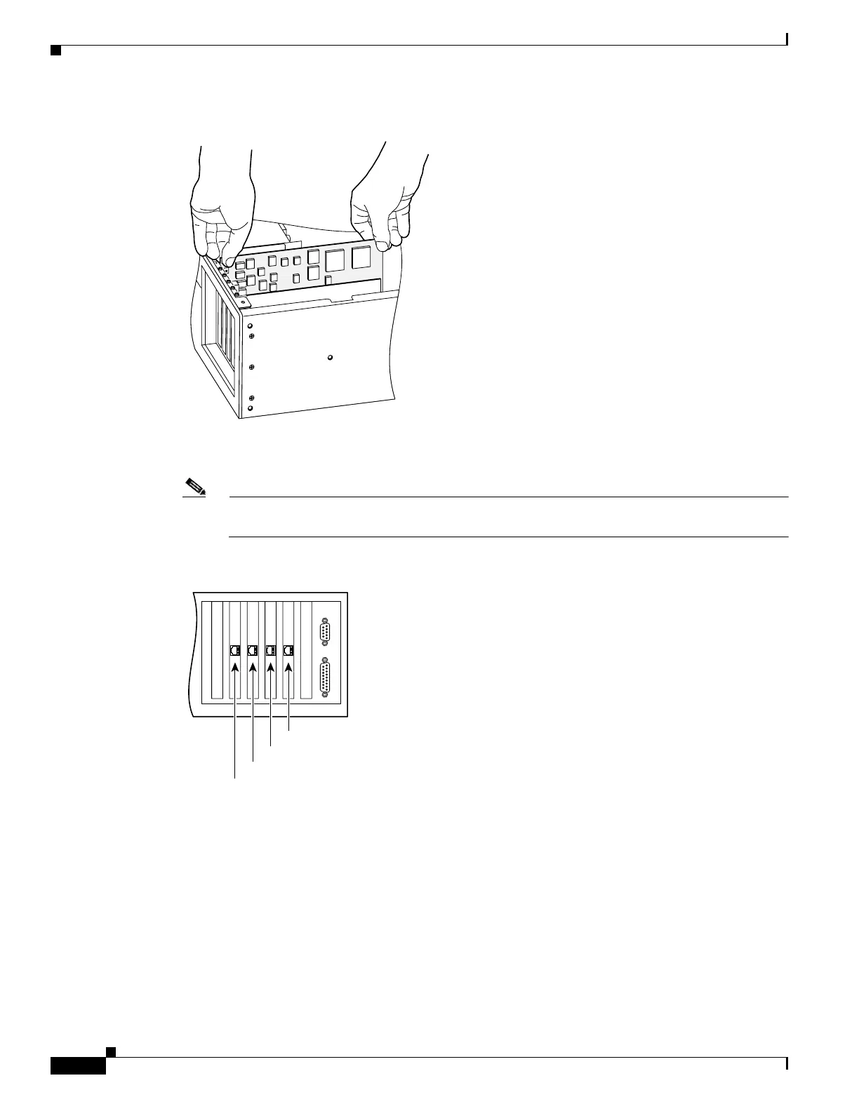
Figure 5-18 Installing the New Circuit Board
Step 3 Figure 5-19 displays how the circuit boards are numbered according to their position. If you have
Version 4.4 and a four-port Ethernet circuit board, refer to “PIX 520 Product Overview”.
Note When adding a network interface or encryption circuit board, install the new circuit board in the
first empty slot to the right of the existing network interface circuit board.
Figure 5-19 PIX Firewall Network Circuit Boards
Step 4 If you are installing a 4-port circuit board, note that the circuit board will overlap the slot connector on
the motherboard. This does not affect the use or operation of the circuit board. Figure 5-20 illustrates
how this appears.
12273
44305
Interface 1
Interface 3
Interface 2
Interface 0
 Loading...


